Rounded die configuration for stress minimization and enhanced thermo-mechanical reliability

Inactive Publication Date: 2009-06-18
NAT SEMICON CORP
View PDF49 Cites 22 Cited by
  • Summary
  • Abstract
  • Description
  • Claims
  • Application Information

AI Technical Summary

Benefits of technology

[0005]In one aspect of the invention, a semiconductor die having rounded sidewall junction edge corn

Problems solved by technology

For example, reducing the sharpness of bottom edge corners formed by the intersection o

Method used


Image

  • Rounded die configuration for stress minimization and enhanced thermo-mechanical reliability
  • Rounded die configuration for stress minimization and enhanced thermo-mechanical reliability
  • Rounded die configuration for stress minimization and enhanced thermo-mechanical reliability

Examples


Embodiment Construction

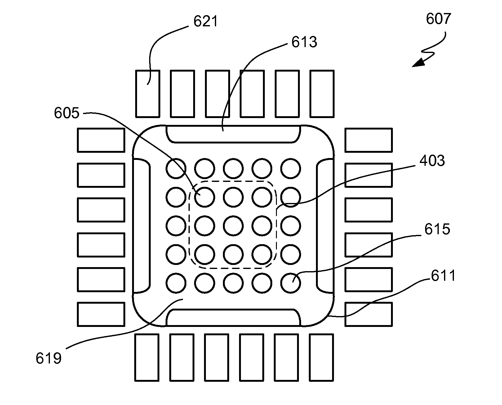
[0026]The present invention relates generally to the packaging of integrated circuit dice. As explained in the background section, the operation and testing of a package subjects the package to substantial stresses. These stresses may affect the performance and reliability of the package. The present invention relates to an improved integrated circuit die with characteristics that help to reduce such stresses.

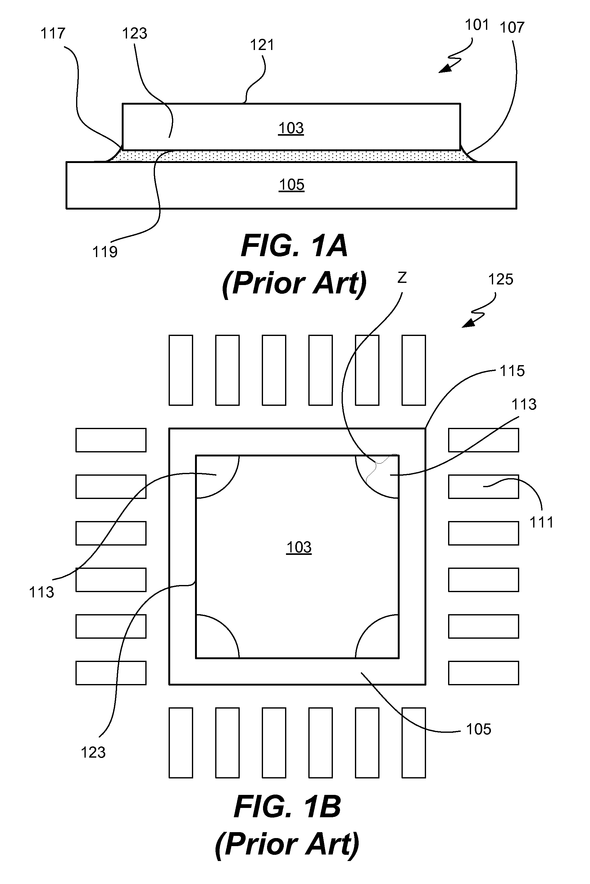
[0027]Referring initially to FIGS. 1A and 1B, a diagrammatic side view 101 and a diagrammatic top view 125 of conventional die 103 mounted on a die attach pad 105 will be described. Conventional die 103 has a top surface 121, sidewalls 123 and bottom surface 119. Contact leads 111 are also shown. Die 103 is mounted upon die attach pad 105. Adhesive 107 secures die 103 to die attach pad 105.

[0028]Conventional die 103 has a rectangular profile with substantially sharp edges and corners. Examples of such corners are corners 115 and 117 in FIGS. 1A and 1B. Sidewall junction edge co...


PUM


Abstract

One aspect of the invention pertains to a semiconductor die with rounded sidewall junction edge corners. Such rounding reduces stress accumulations at those corners. In other embodiments of the invention, the sharpness of other corners and edges in the die are reduced. For example, reducing the sharpness of the bottom edge corners formed by the intersection of a sidewall and the back surface of a die can further diminish stress accumulations. One embodiment pertains to a wafer carried on a wafer support, where the wafer includes a multiplicity of such dice. Another embodiment involves a semiconductor package containing such dice. Methods of fabricating the dice are also described.

Description

BACKGROUND OF THE INVENTION[0001]The present invention relates generally to integrated circuit devices (ICs). More particularly, the invention relates to improved semiconductor dice.[0002]There are a number of conventional processes for packaging integrated circuit (IC) dice. Many packaging techniques contemplate mounting the die on a carrier such as a metallic leadframe, a substrate or a chip carrier. In many packaging arrangements, the back surface of the die is physically attached to the carrier by means of a suitable adhesive material. The die is then typically electrically connected to the leadframe leads or substrate traces and / or other package components by appropriate connectors such as bonding wires. Often, the die, the electrical connectors and portions of the leadframe / substrate are encapsulated with a molding material to protect the electrical connections and the delicate electrical components on the active side of the die.[0003]During testing and operation, the encapsul...

Claims


Application Information

Patent Timeline
IPC IPC(8): H01L29/06H01L21/304H01L23/495
CPCH01L24/32H01L29/0657H01L2224/48257H01L2224/48247H01L2924/01033H01L2924/01006H01L2924/14H01L2924/10158H01L2924/01082H01L2224/83385H01L2224/83365H01L2224/83051H01L2224/73265H01L2224/32245H01L2224/48091H01L2924/00014H01L2924/00H01L2924/3512H01L2924/10155
Inventor NGUYEN, LUU T.GUMASTE, VIJAYLAXMI
Owner NAT SEMICON CORP
Why Eureka
Try Eureka