Battery grid with varied corrosion resistance

A corrosion-resistant, grid technology, applied in the battery field, can solve the problems of limited battery space, limited grid, damaged capacity and high-rate performance, etc., to achieve the effect of reducing stress accumulation

Active Publication Date: 2014-10-22
CPS TECH HLDG LLC
View PDF4 Cites 5 Cited by
  • Summary
  • Abstract
  • Description
  • Claims
  • Application Information

AI Technical Summary

Problems solved by technology

However, the disadvantage of the above solution is the increase of material and cost
[0010] Conventional grid designs often limit the size of the openings in the grid due to manufacturing constraints and / or to ensure that the wet paste remains within the grid structure
Also, in many applications, larger battery sizes may not be desirable or possible due to limited battery space allowed by vehicle manufacturers
Additionally, while making the individual plates smaller within existing battery compartments would provide the space needed for grid expansion, capacity and high-rate performance may suffer in this way
Therefore, the flexibility to provide more space within the container to accommodate grid growth is limited in conventional lead-acid batteries

Method used


Image

  • Battery grid with varied corrosion resistance
  • Battery grid with varied corrosion resistance
  • Battery grid with varied corrosion resistance

Examples


Embodiment 1

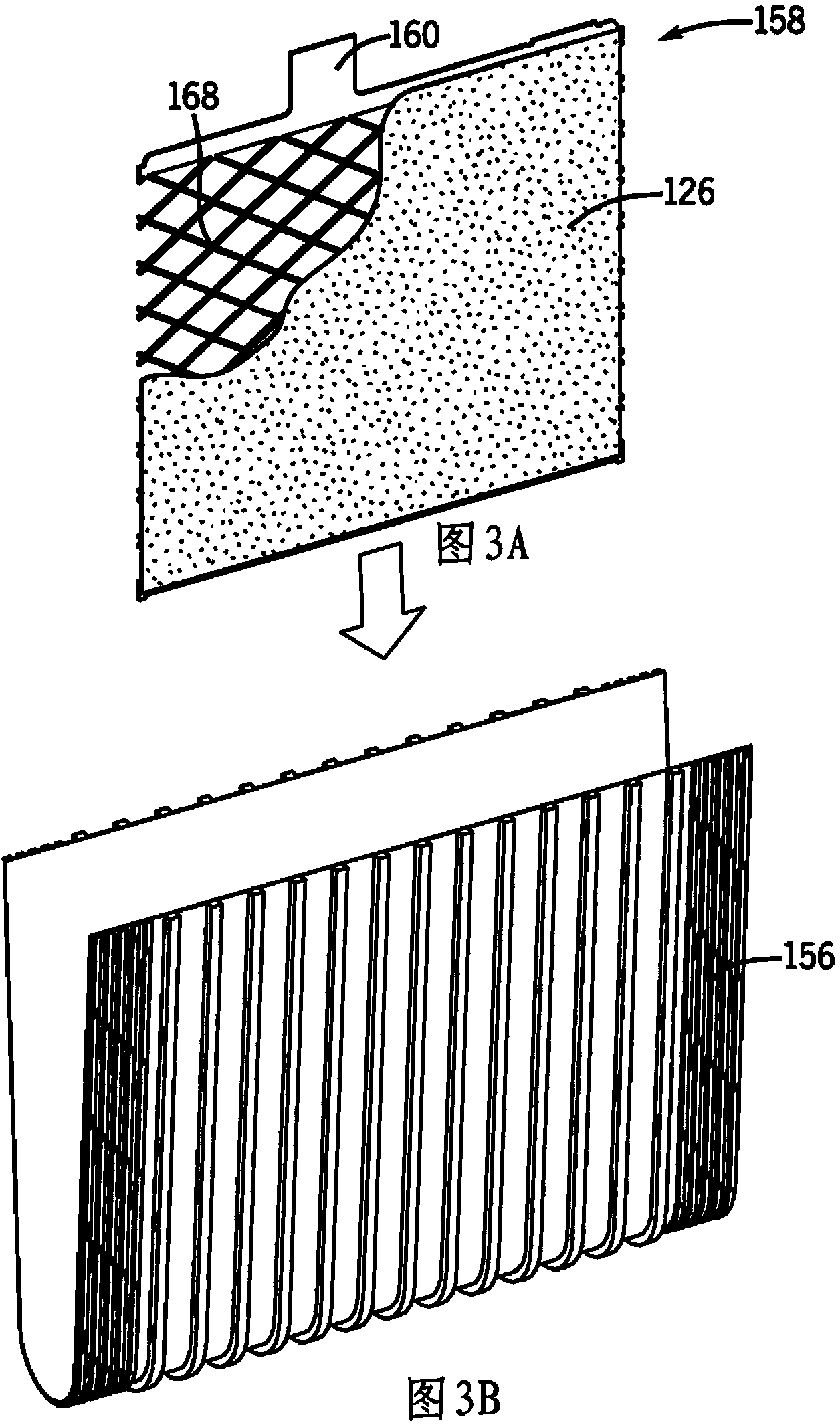
[0112] Exemplary examples of the degree of secondary deformation or corrosion resistance and their effects are given below.

[0113] Bare (uncoated) stamped battery grids formed from wrought lead are available. Fifty percent (50%) secondary deformation of the grid wires is provided on the stamped battery grid. That is, the deformation of the grid wire causes it to change fifty percent (50%) from its original stamped shape. Deformation is done by presses that change the shape and thickness of the segments of the grid wire. A secondary deformation of fifty percent corresponds to the resulting first accelerated corrosion rate or corrosion resistance. Note that the acceleration of the corrosion rate is relative to grid wires that do not undergo secondary deformation. A secondary deformation of thirty-five percent (35%) was also set and done according to the same general process. A secondary deformation of thirty-five percent corresponds to a resulting secondary corrosion resis...

Embodiment 2

[0127] The following examples illustrate hypothetical relationships between grid thickness and percent deformation or corrosion resistance. The percent deformation and the amount of corrosion resistance depend on the initial thickness of the grid.

[0128] In one embodiment, a grid having an initial grid wire thickness of 0.050 inches is subjected to 50% deformation of the grid wires resulting in a final thickness of the grid wires of 0.025 inches. A grid with an initial grid wire thickness of 0.075 inches was subjected to 50% deformation of the grid wires, resulting in a final thickness of the grid wires of approximately 0.038 inches. Likewise, a grid with an initial grid wire thickness of 0.050 inches is subjected to a 30% deformation of the grid wires to provide a final thickness of the grid wires of 0.035 inches, or to an 80% deformation of the grid wires to provide a final thickness of is 0.010 inches. A grid with an initial grid wire thickness of 0.075 inches was subje...

Embodiment 3

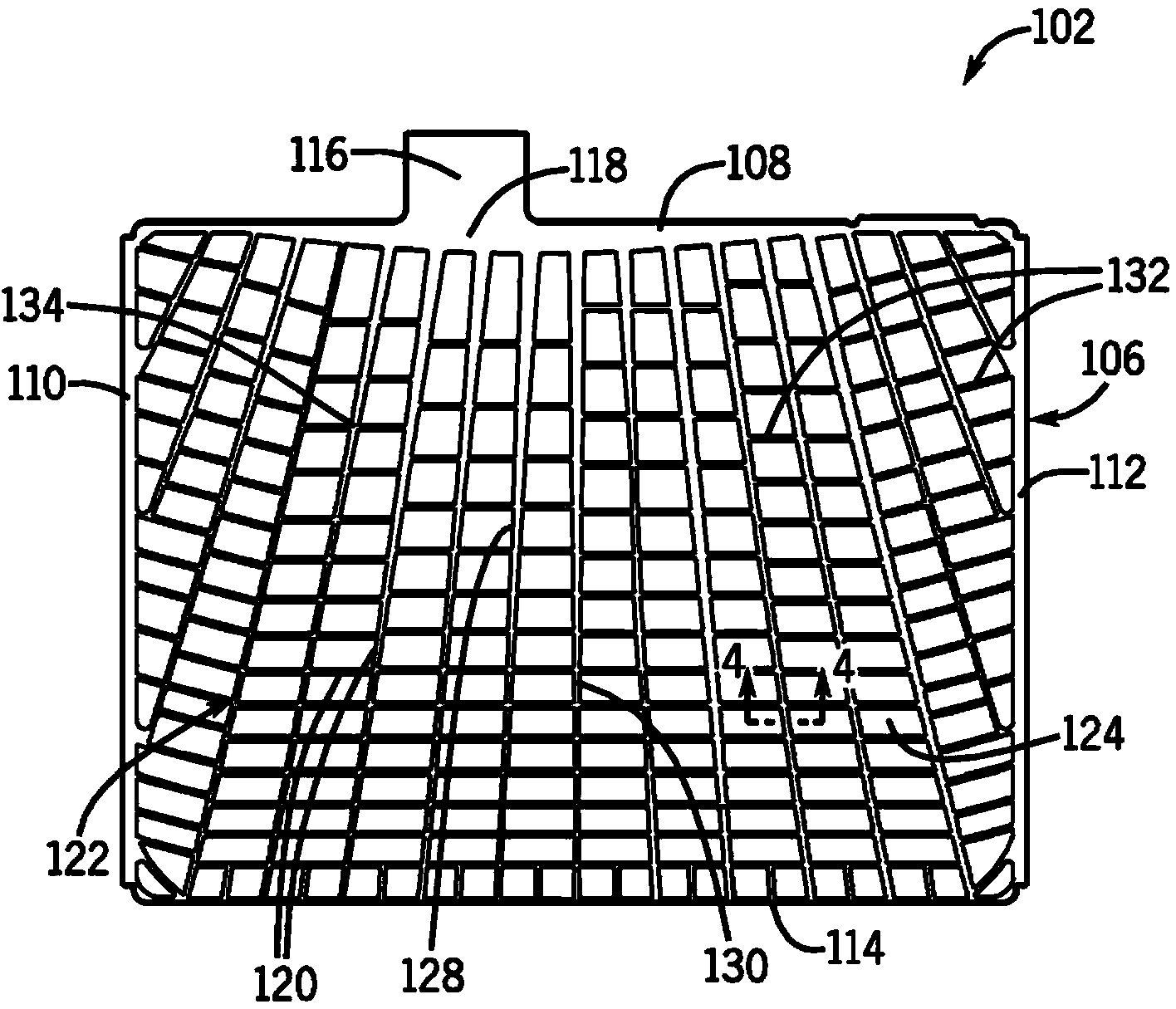
[0130] In one example of an embodiment, one or more of the battery grids has x voids. Each void is bounded by a continuous length of grid wire. In this example, the number of voids is less than x after the positive grid plate is expected to grow within the battery case.


PUM

PropertyMeasurementUnit
thicknessaaaaaaaaaa

Abstract

A battery grid is disclosed. The battery grid includes a pattern of grid wires. The pattern includes a grid wire having a first segment with a first corrosion resistance and a second segment with a second corrosion resistance which is less than the first corrosion resistance. The second segment corrodes at a rate which is faster than the corrosion rate of the first segment so as to dynamically release internal stress and control grid growth of the battery grid during its service life. A battery includes said grid and a method of forming said grid are also disclosed.

Description

[0001] Cross References to Related Applications [0002] This application claims U.S. Provisional Patent Application Serial No. 61 / 555,276, filed November 3, 2011, entitled ENHANCED POSITIVE BATTERY GRID, and U.S. Nonprovisional Patent Application Serial No. 13 / 663,872, filed October 30, 2012 application (titled BATTERY GRID WITH VARIED CORROSION RESISTANCE), the contents of which are hereby incorporated by reference in their entirety. technical field [0003] The present invention relates to the field of batteries (eg, lead-acid batteries, including batteries for vehicle starting, lighting and ignition applications; marine batteries; commercial batteries; industrial batteries; batteries for use in hybrid electric vehicles, micro-hybrid vehicles, etc.). The present invention more particularly relates to battery grids and methods of making battery grids. Background technique [0004] A secondary or rechargeable battery, accumulator or accumulator is a set of one or more elec...

Claims


Application Information

Patent Timeline
Patent Type & Authority Applications(China)
IPC IPC(8): H01M4/72H01M4/74
CPCH01M4/20H01M4/82H01M4/73H01M4/72H01M4/74Y10T29/10Y02E60/10H01M10/06H01M2300/0011
Inventor M.·艾瑞克·泰勒胡建勋格伦·W.·安徒生约瑟夫·F.·马修斯巴特·W.·萨奥尔詹姆斯·S.·塞门斯基薛峰默罕默德海尔·阿尔卡提布
Owner CPS TECH HLDG LLC
Why Eureka
Try Eureka