
Image processing device, imaging device, image processing method, and image processing program

a technology of image processing and imaging device, applied in image enhancement, image analysis, instruments, etc., can solve the problems of inaccurate frequency characteristics of input images, adverse effects, and generation of artifacts, so as to prevent over-correction and improve the image quality of original image data

Inactive Publication Date: 2017-01-05
FUJIFILM CORP
View PDF8 Cites 20 Cited by
  • Summary
  • Abstract
  • Description
  • Claims
  • Application Information

AI Technical Summary

Benefits of technology

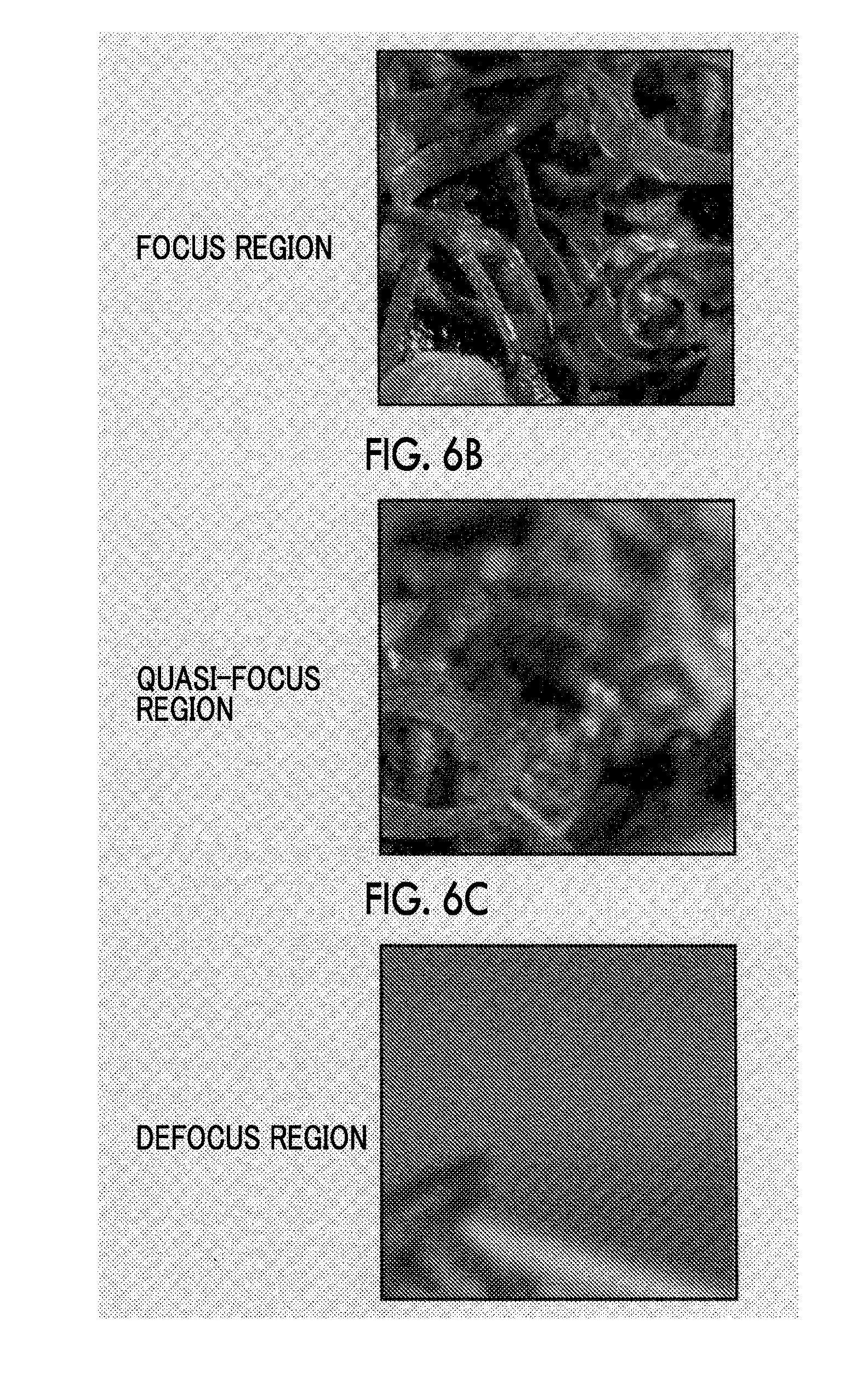
The present invention aims to improve image quality by restoring degraded image data due to the PSF of an optical system. Quasi-focus region in the original image is detected and the restoration rate for the data of this region is adjusted to be smaller than the restoration rate for the focus region. This prevents over-correction and improves the image quality of the quasi-focus region.

Problems solved by technology

In actual processing, however, the frequency characteristics of the input image may be incorrect due to individual variations in lenses or sensors, non-linear characteristics of signal processing before the point image restoration processing, and the like.
As a result, artifacts may be generated.
As one of such phenomena, if the point image restoration processing is applied to an image region deviating from the focus region, an adverse effect that image quality is degraded may occur.
On the other hand, the present inventors have found out through intensive study that an adverse effect that artifacts, such as noise, become noticeable occurs if the same point image restoration processing as for the image of the focus region is performed on an image of a region (quasi-focus region) at a point slightly in front or behind the focus region.
In addition, determining how large a quasi-focus region, in which such an adverse effect is likely to occur, is and extracting the quasi-focus region from the image data has not been considered conventionally.

Method used


Image

  • Image processing device, imaging device, image processing method, and image processing program
  • Image processing device, imaging device, image processing method, and image processing program
  • Image processing device, imaging device, image processing method, and image processing program

Examples


first embodiment

of a Quasi-Focus Region Detection Unit

[0139]Next, a first embodiment of the quasi-focus region detection unit 50 shown in FIG. 4 will be described.

[0140]FIG. 8 is a block diagram showing a first embodiment of the quasi-focus region detection unit 50 that detects a quasi-focus region corresponding to the definition 1 of the quasi-focus described above. The quasi-focus region detection unit 50 of the first embodiment is configured to include a band pass filter (BPF1) 50a, a summing unit 50b, and a determination unit 50c.

[0141]The band pass filter 50a that is a form of a frequency component extraction unit passes frequency components near a specific frequency including the specific frequency (specifically, frequency components of 0.05 fs (326 TV lines) to 0.25 fs (1632 TV lines)), among the frequency components of original image data (input image). The summing unit 50b sums the absolute values of the frequency components input from the band pass filter 50a for each separate region, wh...

second embodiment

[0191]FIG. 20 is a block diagram showing an example of the configuration of an image processing unit 35-2 of a second embodiment that replaces the image processing unit 35 shown in FIG. 3.

[0192]The image processing unit 35-2 includes a sharpness restoration control unit 37-2, a restoration processing unit 38, and an outline enhancement processing unit 39 that functions as a sharpening processing unit that is not based on the point spread function. The restoration processing unit 38 is similar to the restoration processing unit 38 of the image processing unit 35 shown in FIG. 3. Accordingly, the detailed explanation thereof will be omitted.

[0193]The outline enhancement processing unit 39 performs sharpening processing using a sharpening filter, which is not based on the point spread function, on image data. The sharpening filter is not particularly limited if a filter reflecting the point spread function directly is not used, and a known outline enhancement filter can be used as a sh...

third embodiment

[0239]FIG. 23 is a diagram showing the configuration of a processing block that performs point image restoration processing and sharpening processing according to a third embodiment. The same configurations as in the second embodiment shown in FIG. 22 are denoted by the same reference numerals, and the detailed explanation thereof will be omitted.

[0240]A sharpness restoration control unit 37-3 according to the third embodiment acquires a sharpening rate in the sharpening processing, and calculates a “restoration rate” in the point image restoration processing based on the total sharpness restoration rate and the sharpening rate.

[0241]The sharpening rate (sharpening strength magnification V) is input to the sharpness restoration control unit 37-3 (automatic strength adjustment unit 52-3). The sharpening strength magnification V input to the automatic strength adjustment unit 52-3 is designated in advance by the user before the image processing in the restoration processing unit 38 an...


PUM


Abstract

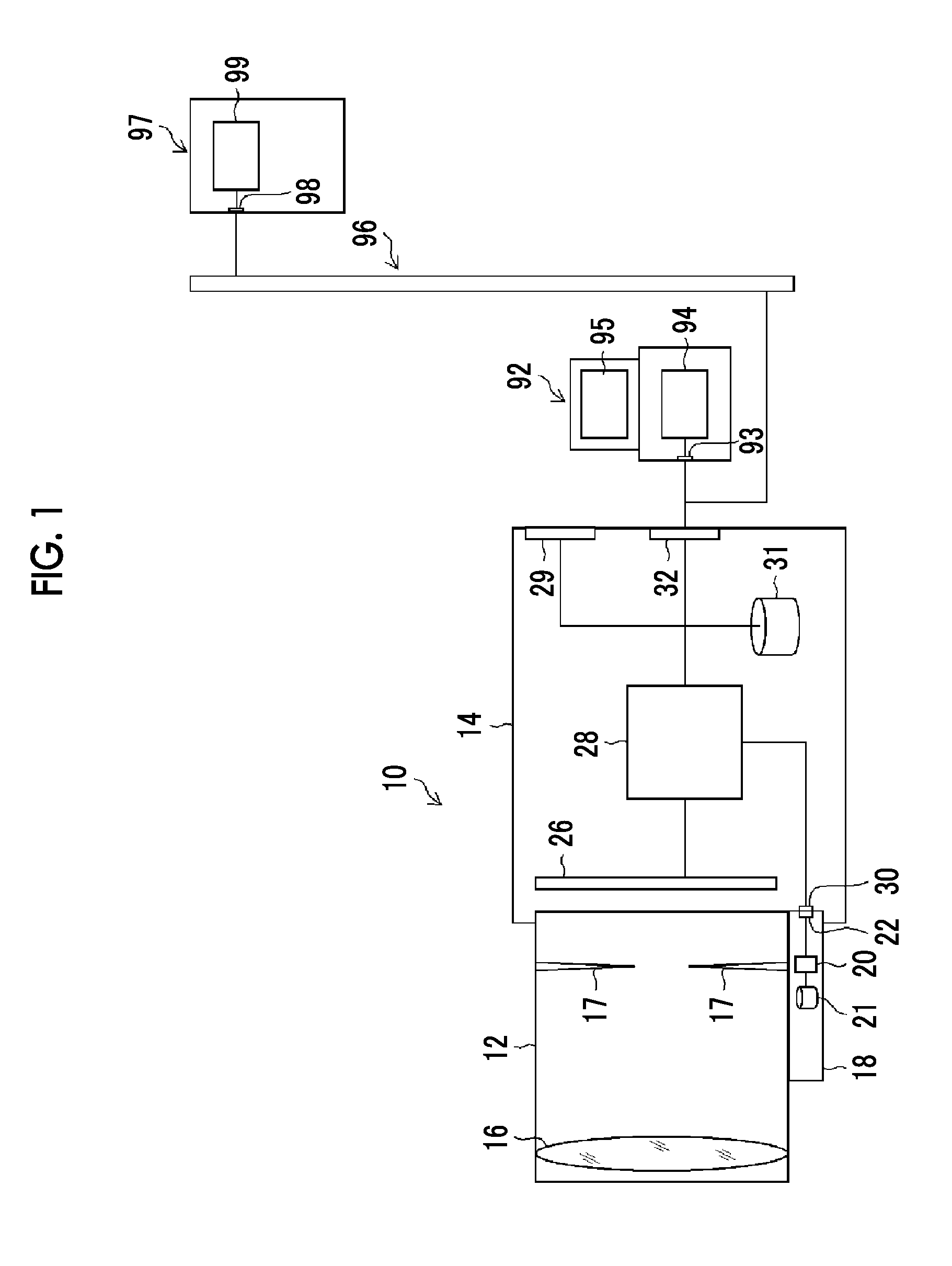
There is provided an image processing device that acquires restored image data by performing restoration processing using a restoration filter based on the PSF of an optical system for original image data acquired by capturing a subject image using the optical system. This device includes a restoration processing unit 38 that performs restoration processing by applying the restoration filter to the original image data, a quasi-focus region detection unit 50 that detects a quasi-focus region in an original image corresponding to the original image data, and a sharpness restoration control unit 37. The sharpness restoration control unit adjusts the restoration strength magnification U for original image data of the detected quasi-focus region so as to be smaller than the restoration strength magnification U for original image data of at least a focus region.

Description

CROSS-REFERENCE TO RELATED APPLICATIONS[0001]This application is a Continuation of PCT International Application No. PCT / JP2015 / 054407 filed on Feb. 18, 2015, which claims priority under 35 U.S.C §119(a) to Patent Application No. 2014-068422 filed in Japan on Mar. 28, 2014, all of which are hereby expressly incorporated by reference into the present application.BACKGROUND OF THE INVENTION[0002]1. Field of the Invention[0003]The present invention relates to an image processing device, an imaging device, an image processing method, and a non-transitory computer readable medium storing an image processing program, and in particular, relates to a method of adjusting the restoration strength according to a focusing situation or a method of adjusting the restoration strength and the sharpening strength.[0004]2. Description of the Related Art[0005]In a subject image captured through an optical system, a point spread phenomenon may be observed in which a point subject has a very small sprea...

Claims


Application Information

Patent Timeline
IPC IPC(8): G06T5/00G06T5/20
CPCG06T5/20G06T2207/20012H04N23/80G06T5/73H04N23/951H04N23/959G06T2207/10004
Inventor IRIE, KOSUKENARUSE, YOUSUKEHAYASHI, KENKICHI
Owner FUJIFILM CORP
Learn More