Compact planetary gearbox

A transmission device and planetary gear technology, which is applied to gear transmission devices, transmission devices, transmission device parts, etc., can solve problems such as the need for axial structural space, and achieve the effect of saving structural space and reducing axial structural space

Inactive Publication Date: 2017-12-15
ZF FRIEDRICHSHAFEN AG
View PDF0 Cites 0 Cited by
  • Summary
  • Abstract
  • Description
  • Claims
  • Application Information

AI Technical Summary

Problems solved by technology

This is problematic because the mounting of the planetary carrier and the double row of spur gears requires axial construction space

Method used


Image

  • Compact planetary gearbox

Examples


Embodiment Construction

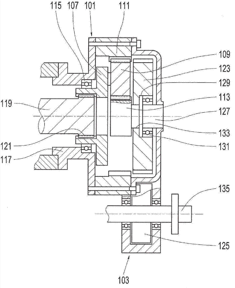
[0019] figure 1 The transmission shown has an input-side planetary gear stage 101 and an output-side spur gear stage 103 . The planetary gear stage 101 comprises a planet carrier 107 , planet gears 109 rotatably mounted in the planet carrier 107 , a stationary ring gear 111 and a rotatable sun gear 113 . The planetary gears 109 mesh with the ring gear 111 and the sun gear 113 .

[0020] The planet carrier 107 is rotatably mounted in the transmission housing 117 by means of exactly one bearing 115 . The ring gear 111 forms part of the transmission housing 117 and is screwed to another part of the transmission housing 117 . The bearing 115 is arranged offset with respect to the arms of the planet carrier 107 on the drive side, ie in the direction of the drive shaft 119 .

[0021] A drive torque is applied to the planet carrier 107 via the drive shaft 119 . For this purpose, the drive shaft 119 is connected to the planet carrier 107 in a rotationally fixed manner by means of ...


PUM


Abstract

A transmission having at least one planetary stage (101), at least one spur gear stage (103) and a transmission housing (117). The planetary stage (101) includes a planetary carrier (107) mounted to rotate, one or more planetary gearwheels (109) mounted to rotate on the planetary carrier (107), and a rotatable sun gear (113). The spur gear stage (103) has at least one spur gear (123). The spur gear (123) and the sun gear (113) are rotationally fixedly connected to one another. The transmission housing (117) has at least one spindle (127) and the spur gear (123) is mounted on the spindle (127).

Description

technical field [0001] The invention relates to a transmission according to the preamble of claim 1 . The transmission has a driven planetary gear stage and a downstream spur gear stage. Background technique [0002] In the case of a transmission of this type known from the prior art, the planet carrier of the planetary gear stage is rotatably mounted on the transmission housing in a double row, that is to say by means of at least two bearings arranged on both sides of the planet carrier. middle. The first spur gear of the spur gear stage is driven via the sun gear shaft. The sun shaft projects into the recess of the spur gear and is connected there in a rotationally fixed manner with the spur gear by means of the synchronizing toothing. The spur gear and the planet carrier are likewise mounted rotatably in the transmission housing in a double row, that is to say by means of at least two bearings arranged on both sides of the spur gear. This is problematic because the su...

Claims


Application Information

Patent Timeline
Patent Type & Authority Applications(China)
IPC IPC(8): F16H57/021F16H57/08F16H1/28
CPCF16H1/28F16H57/021F16H57/08F16H37/041F16H1/06F16H55/17F16H57/082
Inventor 弗兰克·里希特卡尔·本克勒马顿·库鲁克兹
Owner ZF FRIEDRICHSHAFEN AG
Why Eureka
Try Eureka