Heat pump system and control method thereof

A technology of a heat pump system and a control method, which is applied in the field of heat pumps, can solve problems such as the waste of the available range of the compressor, the size and specification of the throttling parts, and the inability of the compressor to fully realize the evaporation temperature range, so as to achieve the effect of ensuring energy efficiency

Pending Publication Date: 2017-12-15
GREE ELECTRIC APPLIANCES INC
View PDF3 Cites 7 Cited by
  • Summary
  • Abstract
  • Description
  • Claims
  • Application Information

AI Technical Summary

Problems solved by technology

In the whole refrigeration system, often due to the different sizes and specifications of the throttling parts, the compressor

Method used


Image

  • Heat pump system and control method thereof

Examples


Embodiment Construction

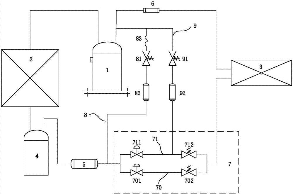
[0028] A first aspect of the present invention provides a heat pump system such as figure 1 As shown, it includes a compressor 1, a condenser 2 and an evaporator 3, wherein a throttling unit 7 is arranged on the flow path between the condenser 2 and the evaporator 3, and the throttling unit 7 includes At least two throttling branches connected in parallel, such as the first throttling branch 70 and the second throttling branch 71 shown in the figure, wherein each throttling branch is provided with a throttling component, such as the first throttling branch A first throttling component 701 is disposed in the branch path 70 , and a second throttling component 711 is disposed in the second throttling branch path 71 . Wherein, the heat pump system makes full use of the evaporation temperature range of the compressor 1 by selecting the number of throttling branches that are turned on, that is, throttling is performed by turning on a single throttling branch or making two or more th...


PUM


Abstract

The invention discloses a heat pump system and a control method of the heat pump system. The heat pump system comprises a compressor, a condenser and an evaporator. A throttling unit is arranged on a flow path between the condenser and the evaporator. The throttling unit comprises at least two throttling branches connected in parallel. Each throttling branch is provided with a throttling component. The evaporation temperature range of the compressor is sufficiently utilized by selecting the number of the connected throttling branches in the heat pump system. The at least two throttling components connected in parallel are arranged in the heat pump system, so that one or two or more throttling components can carry out throttling according to specific working conditions, and therefore the operation range of the compressor is sufficiently utilized.

Description

technical field [0001] The invention relates to the technical field of heat pumps, in particular to a heat pump system and a control method thereof. Background technique [0002] A conventional refrigeration system is mainly composed of four parts: a compressor, a condenser, a throttling component and an evaporator. During the entire operation of the refrigeration system, the compressor sucks the refrigerant vapor generated from the evaporator and sends it to After being compressed to the condensing pressure, the high-temperature and high-pressure refrigerant gas is discharged from the exhaust port, then enters the condenser, isobarically cooled under the condensing pressure and condensed into a refrigerant liquid, and the condensed refrigerant liquid enters the evaporator through the throttling part , the refrigerant passes through the throttling part and becomes a mixed state of gas-liquid two-phase, and then enters the evaporator to exchange heat with the relevant medium ...

Claims


Application Information

Patent Timeline
IPC IPC(8): F25B30/02F25B41/04F25B41/06F25B43/00F25B49/02F25B41/20F25B41/31
CPCF25B30/02F25B43/003F25B49/02F25B41/22F25B41/31
Inventor 邹温锋杨虹李金奎李庆卫广穹刘幸
Owner GREE ELECTRIC APPLIANCES INC
Why Eureka
Try Eureka