Heat pump defrosting exit control method and device, electronic equipment and storage medium

A control method and heat pump technology, applied in the field of heat pumps, can solve the problems such as the decrease of heating efficiency of the unit, increase of energy consumption, failure and so on.

Inactive Publication Date: 2021-05-18
GUANGDONG PHNIX ECO ENERGY SOLUTION
View PDF9 Cites 5 Cited by
  • Summary
  • Abstract
  • Description
  • Claims
  • Application Information

AI Technical Summary

Problems solved by technology

[0003] However, in the heat pump defrosting process at present, it often happens that the frost layer on the evaporator is not completely removed, and the defrosting exit condition is reached.
As a result, the unremoved frost layer on the evaporator will affect the heating capacity of the unit when the heating continues in the next cycle, resulting in a decrease in the heating efficiency of the unit, increasing energy consumption, and failing to meet the water temperature requirements of the heat pump unit
Moreover, due to incomplete defrosting, the frost layer will gradually evolve into an ice layer, resulting in the inability to completely defrost in the next cycle of defrosting.
Even with the passage of time, the ice area will continue to accumulate and expand, which will eventually lead to the failure of the unit to defrost or even malfunction

Method used


Image

  • Heat pump defrosting exit control method and device, electronic equipment and storage medium
  • Heat pump defrosting exit control method and device, electronic equipment and storage medium
  • Heat pump defrosting exit control method and device, electronic equipment and storage medium

Examples


Embodiment 1

[0041] figure 1 A flow chart of a heat pump defrost exit control method provided in Embodiment 1 of the present application is given. The heat pump defrost exit control method provided in this embodiment can be executed by a heat pump defrost exit control device. The heat pump defrost exit control method The device can be realized by means of software and / or hardware, and the heat pump defrosting exit control device can be composed of two or more physical entities, or can be composed of one physical entity. Generally speaking, the heat pump defrosting exit control device may be a heat pump controller device or the like.

[0042] The following description will be made by taking the heat pump defrost exit control device as the main body for executing the heat pump defrost exit control method as an example. refer to figure 1 , the heat pump defrosting exit control method specifically includes:

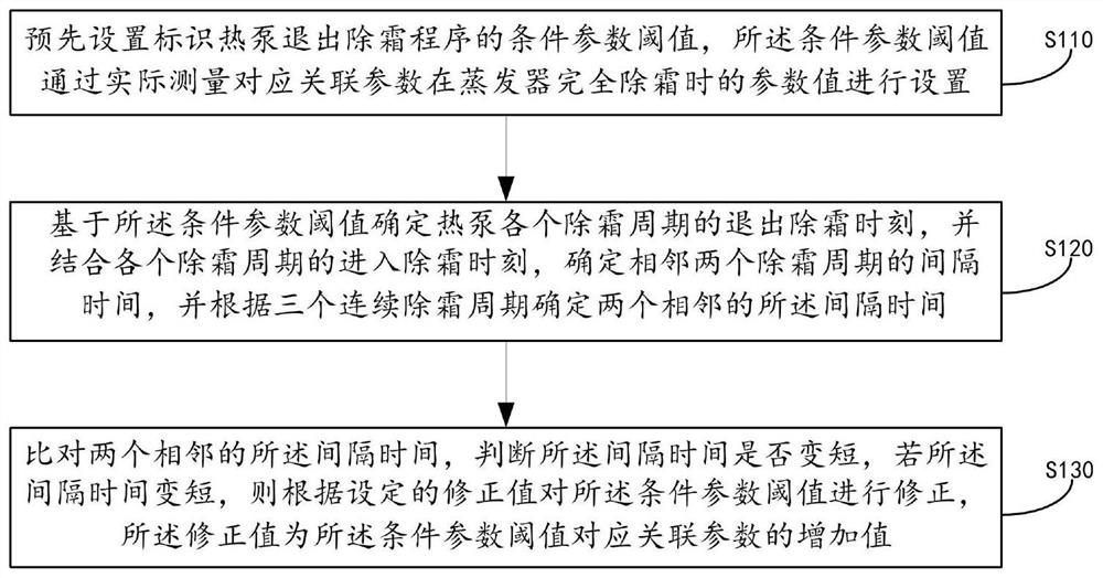
[0043] S110. Preset a condition parameter threshold indicating that the heat pump ...

Embodiment 2

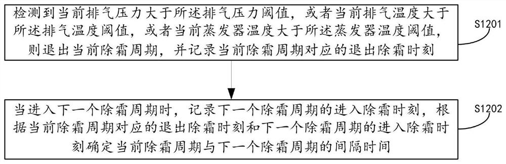
[0064] On the basis of the above-mentioned embodiment, Figure 4 This is a flowchart of another heat pump defrosting exit control method provided in the second embodiment of the present application. refer to Figure 4 , the heat pump defrosting exit control method provided by this embodiment specifically includes:

[0065] S210, preset a conditional parameter threshold that identifies the heat pump exiting the defrosting procedure, and the conditional parameter threshold is set by actually measuring the parameter value of the corresponding associated parameter when the evaporator is completely defrosted;

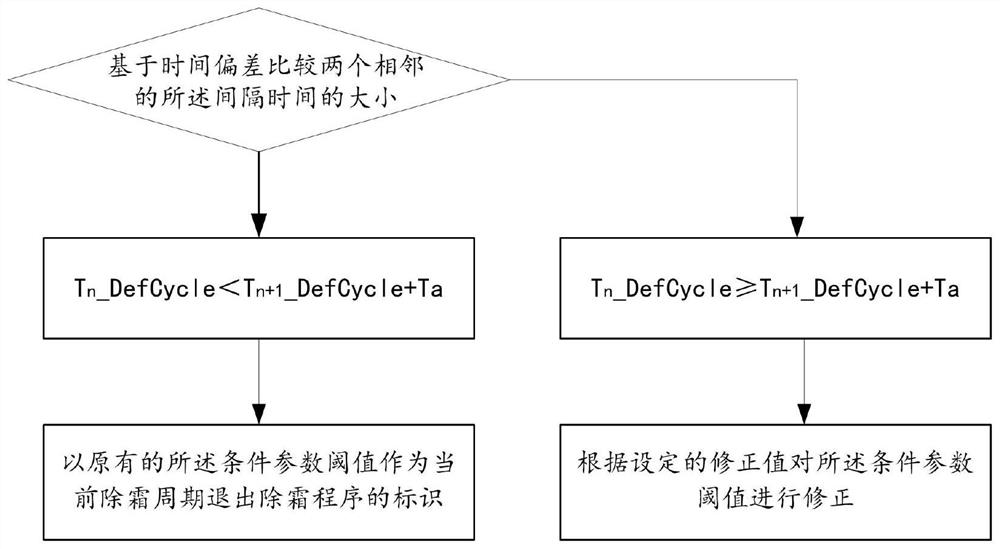
[0066] S220. Determine the exit defrost time of each defrost cycle of the heat pump based on the condition parameter threshold, and determine the interval time between two adjacent defrost cycles in combination with the entry defrost time of each defrost cycle, and determine the interval time between two adjacent defrost cycles according to three consecutive defrost cycles....

Embodiment 3

[0073] On the basis of the above-mentioned embodiment, Figure 5 This is a schematic structural diagram of a heat pump defrosting exit control device provided in Embodiment 3 of the present application. refer to Figure 5 , the heat pump defrosting exit control device provided in this embodiment specifically includes: a setting module 31 , a determination module 32 and a correction module 33 .

[0074] Wherein, the setting module 31 is used to preset a conditional parameter threshold that identifies the heat pump exiting the defrosting procedure, and the conditional parameter threshold is set by actually measuring the parameter value of the corresponding associated parameter when the evaporator is completely defrosted;

[0075]The determination module 32 is used to determine the exit defrost time of each defrost cycle of the heat pump based on the threshold value of the condition parameter, and determine the interval between two adjacent defrost cycles in combination with the...


PUM


Abstract

The embodiment of the invention discloses a heat pump defrosting exit control method and device, electronic equipment and a storage medium. According to the technical scheme provided by the embodiment of the invention, a condition parameter threshold value for identifying that a heat pump exits a defrosting program is preset, a defrosting exiting moment of each defrosting period of the heat pump is determined based on the condition parameter threshold value, interval time between two adjacent defrosting periods is determined by combining a defrosting entering moment of each defrosting period, whether the interval time is shortened or not is judged by comparing two adjacent interval time, and if the interval time is shortened, the condition parameter threshold value is corrected according to a set correction value. By the adoption of the technical means, the defrosting exit condition of the heat pump can be adaptively corrected, the situation that a frost layer of an evaporator can be removed as far as possible is ensured, the situation that the frost layer is accumulated and expanded due to incomplete defrosting is avoided, then the energy efficiency of the heat pump is guaranteed, and operation faults are avoided.

Description

technical field [0001] The embodiments of the present application relate to the technical field of heat pumps, and in particular, to a heat pump defrosting exit control method, device, electronic device, and storage medium. Background technique [0002] During the use of low-temperature heat pumps, the evaporator often freezes. In order not to affect the energy efficiency and normal use of the heat pump, it is necessary to control the heat pump to perform the evaporator self-defrosting operation. During the defrosting process of the heat pump, the timing for the heat pump to exit the defrosting program will be determined according to the preset defrosting exit conditions. When the heat pump reaches the defrosting exit condition, the heat pump will control the exit of the defrosting program, so as to realize the heat pump self-defrosting function. [0003] However, in the current defrosting process of the heat pump, it often occurs that the defrosting exit condition is reach...

Claims


Application Information

Patent Timeline
Patent Type & Authority Applications(China)
IPC IPC(8): F25B49/02F25B47/02
CPCF25B49/02F25B47/02
Inventor 刘志力雷朋飞罗刚蔡鹏城潘群
Owner GUANGDONG PHNIX ECO ENERGY SOLUTION
Why Eureka
Try Eureka