Multi-functional power box

A power box, multi-functional technology, applied in electrical components, substation/distribution device housing, substation/switch layout details, etc., can solve the problems of inconvenient movement, easy to get wet, poor heat dissipation function

Active Publication Date: 2017-12-15
江苏锦秀高压电器有限公司
View PDF7 Cites 5 Cited by
  • Summary
  • Abstract
  • Description
  • Claims
  • Application Information

AI Technical Summary

Problems solved by technology

[0005] In order to overcome the disadvantages of the existing power box that is inconvenient to move, it is easy to get wet in rainy weather, the heat dissipation function is not good, it is easy to cause damage, and the shortcomings increase economic losses. The technical problem to be solved by the invention is to provide a portable , It is not easy to get wet in rainy days, has good heat dissipation function, is not easy to cause damage, and is a multi-functional power box that reduces economic losses

Method used


Image

  • Multi-functional power box
  • Multi-functional power box
  • Multi-functional power box

Examples


Embodiment 1

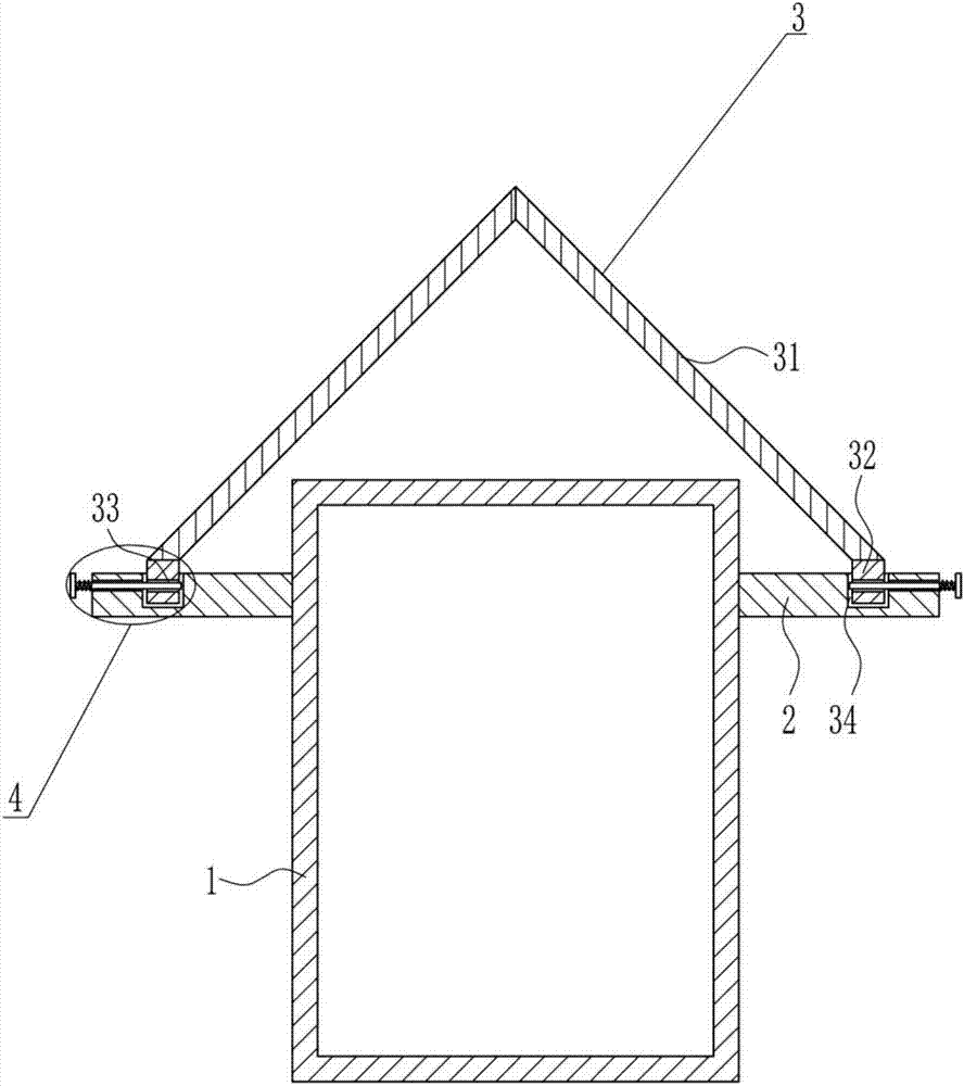
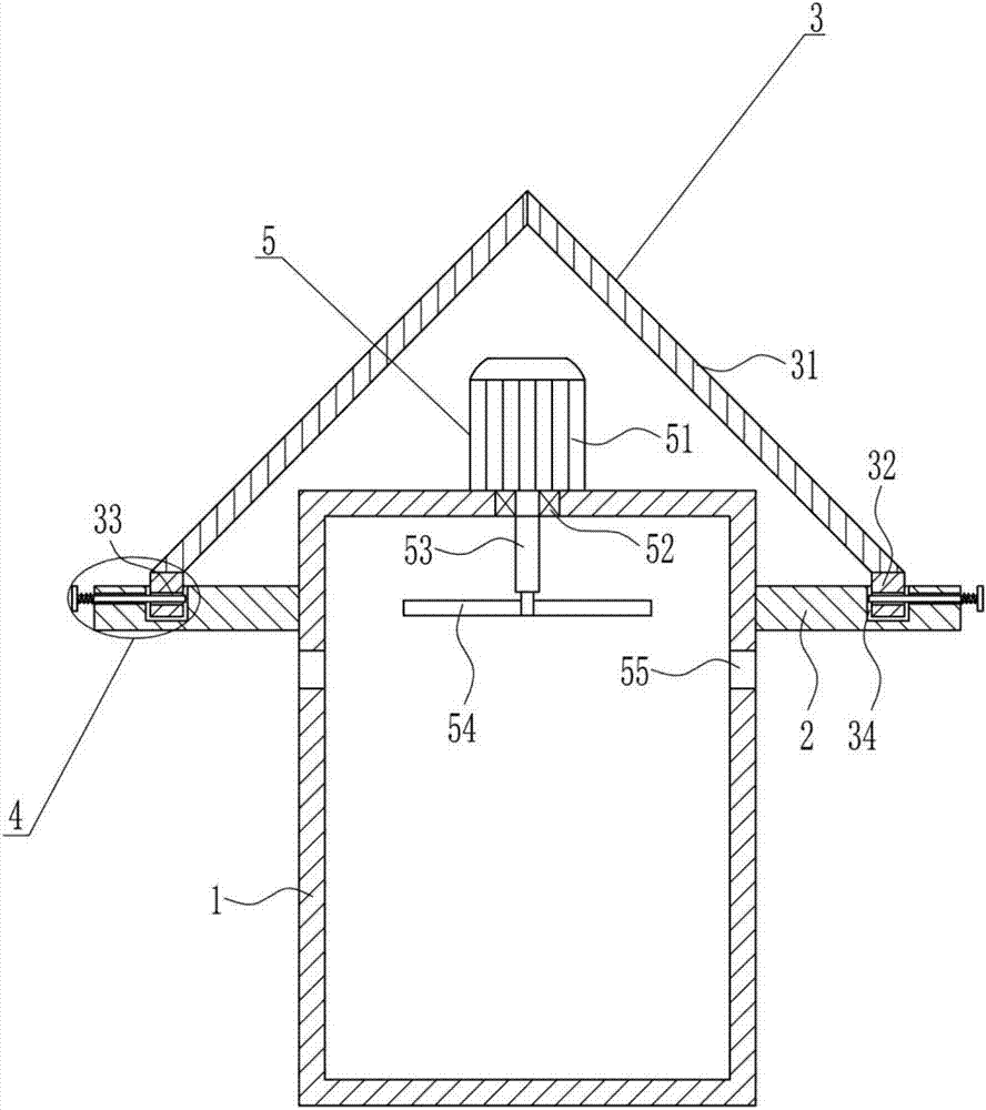
[0037] A multifunctional power box, such as Figure 1-7 As shown, it includes a power box main body 1, a fixed block 2, a water retaining device 3 and a locking device 4. The upper side of the outer surface of the power box main body 1 is horizontally connected with a fixed block 2 by means of bolt connection, and the fixed block 2 is provided with There is a water retaining device 3, the water retaining part of the water retaining device 3 is located directly above the main body 1 of the power box, and the fixing block 2 outside the water retaining device 3 is provided with a locking device 4, which cooperates with the water retaining device 3 .

Embodiment 2

[0039] A multifunctional power box, such as Figure 1-7 As shown, it includes a power box main body 1, a fixed block 2, a water retaining device 3 and a locking device 4. The upper side of the outer surface of the power box main body 1 is horizontally connected with a fixed block 2 by means of bolt connection, and the fixed block 2 is provided with There is a water retaining device 3, the water retaining part of the water retaining device 3 is located directly above the main body 1 of the power box, and the fixing block 2 outside the water retaining device 3 is provided with a locking device 4, which cooperates with the water retaining device 3 .

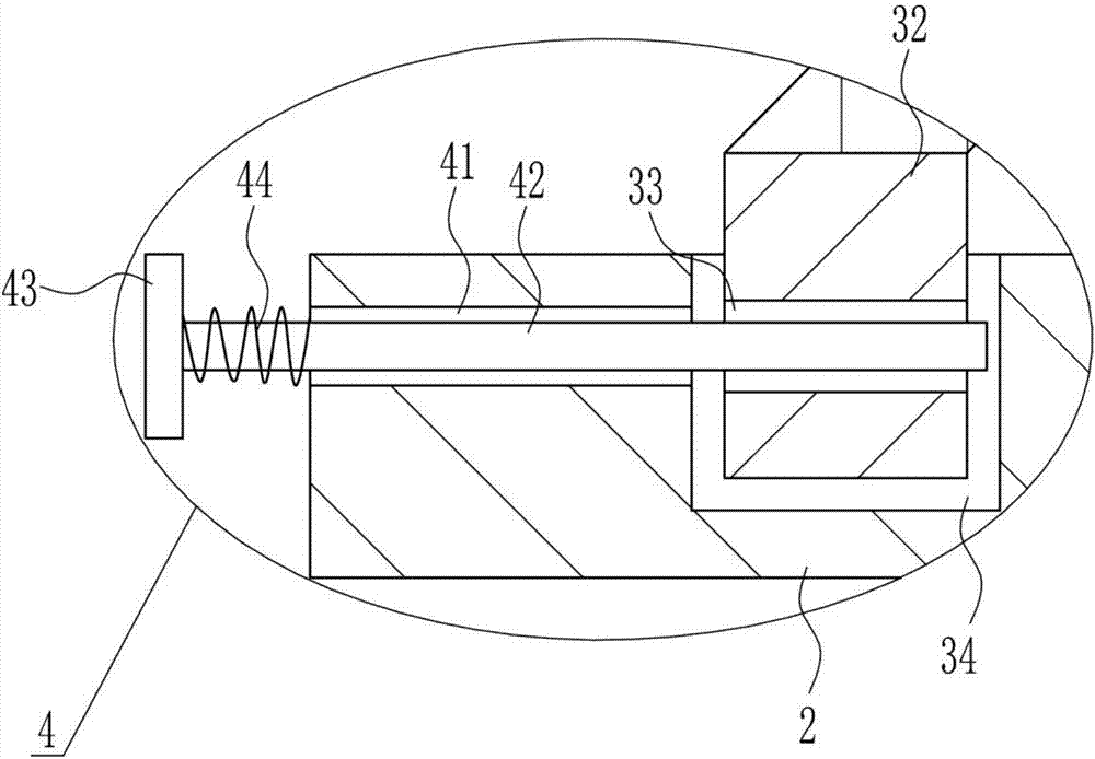
[0040] The water retaining device 3 includes a sloping plate 31 and a block 32. The fixed block 2 is provided with a slot 34. The slot 34 is provided with a block 32. The block 32 cooperates with the slot 34. The top of the block 32 is connected by bolts. The two slant plates 31 are connected directly above the main body 1 of the p...

Embodiment 3

[0042] A multifunctional power box, such as Figure 1-7 As shown, it includes a power box main body 1, a fixed block 2, a water retaining device 3 and a locking device 4. The upper side of the outer surface of the power box main body 1 is horizontally connected with a fixed block 2 by means of bolt connection, and the fixed block 2 is provided with There is a water retaining device 3, the water retaining part of the water retaining device 3 is located directly above the main body 1 of the power box, and the fixing block 2 outside the water retaining device 3 is provided with a locking device 4, which cooperates with the water retaining device 3 .

[0043] The water retaining device 3 includes a sloping plate 31 and a block 32. The fixed block 2 is provided with a slot 34. The slot 34 is provided with a block 32. The block 32 cooperates with the slot 34. The top of the block 32 is connected by bolts. The two slant plates 31 are connected directly above the main body 1 of the p...


PUM


Abstract

The present invention relates to an electric box, especially to a multi-functional power box. The objective of the invention is to provide a multi-functional power box which is convenient to move, is not easy to get wet in a rainy day, is good in heat dissipation function, is not easy to cause damage and can reduce economic loss. In order to reach the objective, the present invention provides a multi-functional power box. The multi-functional power box comprises a power box main body and the like. Fixed blocks are bilaterally symmetrically arranged and horizontally connected at the upper portion of the outer side surface of the power box main body through the bolt connection mode, the fixed blocks are provided with a water retaining device, the water retaining part of the water retaining device is located above the power box main body, the fixed blocks located at the outer side of the water retaining device are provided with locking devices, and the locking devices are matched with the water retaining device. The water retaining device is fixed through the locking devices to facilitate maintenance and cleaning and reach the effect that the multi-functional power box is convenient to move, is not easy to get wet in a rainy day, is good in heat dissipation function, is not easy to cause damage and can reduce economic loss.

Description

technical field [0001] The invention relates to an electric box, in particular to a multifunctional electric box. Background technique [0002] Power chassis are mostly used to load instruments, meters, electronics, communications, automation, sensors, smart cards, industrial control, precision machinery and other items. Most of the materials are high-quality aluminum alloy profiles. Aluminum alloy profiles have firm structure, beautiful appearance, and good heat dissipation. And other characteristics, it is an ideal box for high-end instruments. [0003] The existing power box is inconvenient to move, it is easy to get wet in rainy weather, the heat dissipation function is not good, it is easy to cause damage, and the economic loss is increased. A multi-functional power box that is not easy to cause damage and reduces economic losses. Contents of the invention [0004] (1) Technical problems to be solved [0005] In order to overcome the disadvantages of the existing p...

Claims


Application Information

Patent Timeline
Patent Type & Authority Applications(China)
IPC IPC(8): H02B1/46H02B1/28
CPCH02B1/28H02B1/46
Inventor 王静娴陈爱玲廖敬友
Owner 江苏锦秀高压电器有限公司
Why Eureka
Try Eureka