Nut punching riveting die

A stamping riveting and nut technology, which is applied in forming tools, manufacturing tools, metal processing equipment, etc., can solve the problems of low production efficiency, easy cracking of welds, poor stability, etc., and achieve high production efficiency and firm riveting effect

Inactive Publication Date: 2017-12-19
福州金鸿顺汽车部件有限公司
View PDF5 Cites 2 Cited by
  • Summary
  • Abstract
  • Description
  • Claims
  • Application Information

AI Technical Summary

Problems solved by technology

However, this process has the following disadvantages: 1) It is easy to desolder and the strength is not good, because once there is a deviation in the welding or pores are generated during the welding process, the welding strength is insufficient, and the weld is easy to crack under the premise of load torque
2) The stability is poor, because manual welding is easy to produce eccentricity between the stamping part and the nut, and the stability is poor
3) The production efficiency is low, and it takes a long time to artificially weld the circle of the nut

Method used


Image

  • Nut punching riveting die
  • Nut punching riveting die
  • Nut punching riveting die

Examples


Embodiment Construction

[0020] Specific embodiments of the present invention will be described in detail below in conjunction with the accompanying drawings.

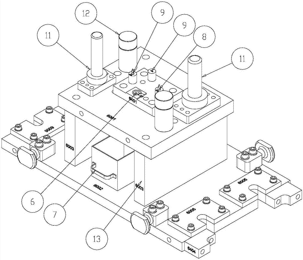
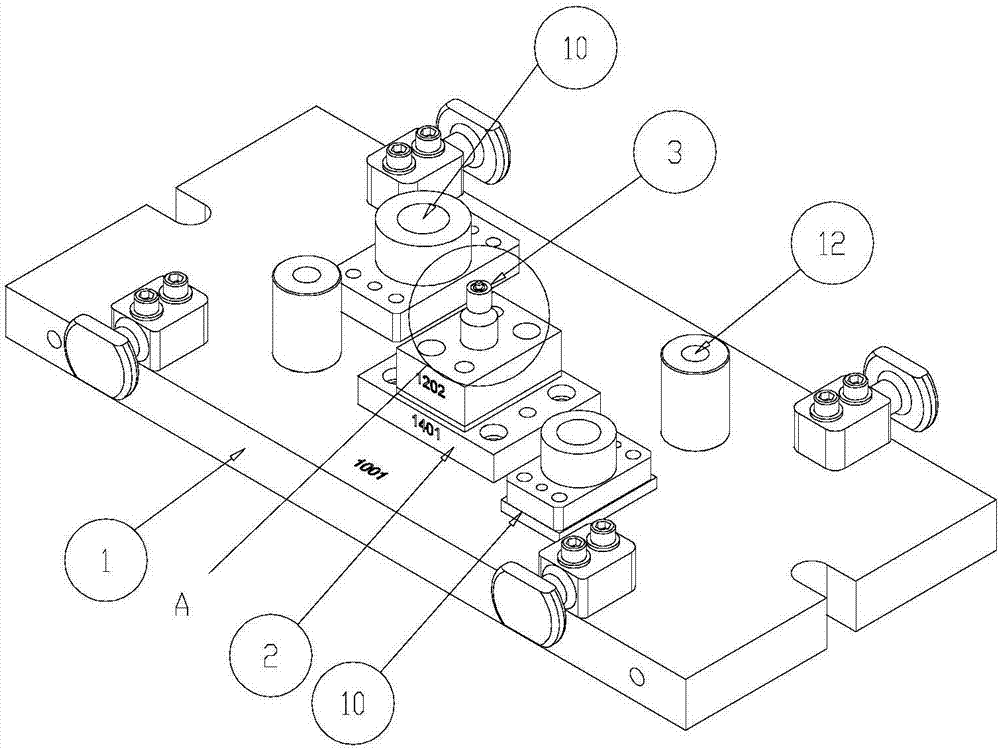
[0021] Such as Figure 1-3 As shown, a nut stamping riveting die includes an upper mold base 1 and a lower mold base 13 .

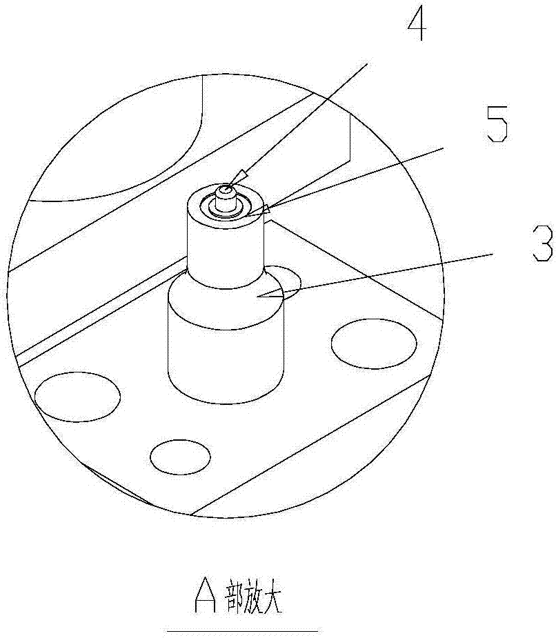
[0022] The upper die base 1 is provided with an upper installation seat 2, and the upper installation seat 2 is provided with a riveting punch 3. The riveting punch 3 is provided with a stepped through hole with a large upper part and a smaller one at the lower part. The ejector pin 4 is provided with a nitrogen spring (not shown) that pushes the ejector pin 4 in the upper mounting seat 2, and the ring magnet 5 that absorbs the nut is provided at the bottom of the riveting punch 3 . The lower die base 13 is provided with a riveting die cover 6, and the riveting die cover 6 is provided with a waste discharge hole, and the lower die base 13 is detachably provided with a waste box 7 below the riveting die cover 6. The lowe...


PUM


Abstract

The invention discloses a nut punching and riveting mold with high stamping efficiency and good riveting effect. There is a stepped through hole with a large upper part and a smaller one at the lower part. A stepped shaft-shaped ejector pin is pierced through the stepped through hole. A nitrogen spring for pushing the ejector pin is provided in the upper mounting seat, and an adsorption nut is provided at the bottom of the riveting punch. The ring magnet is provided with a riveting die set in the lower die base, a waste material discharge hole is arranged in the riveting die set, and at least two positioning pins for positioning workpieces are arranged on the lower die base.

Description

technical field [0001] The invention relates to a nut stamping and riveting die. Background technique [0002] When nuts are set on the stamped plate for connection, the plate and the nut are connected by spot welding first, and then the stamped plate and the nut are positioned with a professional fixture, and then welded to connect the two as a whole. However, this process has the following disadvantages: 1) It is easy to desolder, and the strength is not good, because once there is a deviation in the welding or pores are generated during the welding process, the welding strength is insufficient, and the weld is easy to crack under the load torque premise. 2) The stability is poor, because manual welding is easy to produce eccentricity between the stamping part and the nut, and the stability is poor. 3) The production efficiency is low, and it takes a long time to artificially weld the circle of the nut. Contents of the invention [0003] The technical problem to be sol...

Claims


Application Information

Patent Timeline
IPC IPC(8): B21D37/10B21D37/12B21D39/00
CPCB21D37/10B21D37/12B21D39/00
Inventor 徐锋来
Owner 福州金鸿顺汽车部件有限公司
Why Eureka
Try Eureka