

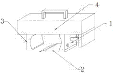
Simple clamp for industrial machinery
A kind of industrial machinery, simple technology, applied in the direction of workpiece clamping device, manufacturing tools, etc., can solve the problems of difficult control of clamping force, poor unloading protection, hard collision of pipelines, etc., to achieve improved buffer protection performance and complete functions , to avoid the effect of collision deformation
- Summary
- Abstract
- Description
- Claims
- Application Information
AI Technical Summary
Problems solved by technology
Method used
Image

Examples
specific Embodiment approach
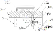
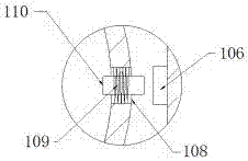
[0026] Specific implementation method: the operator first fits the pipeline with the right end surface of the fixed arc-shaped splint 3, and runs the electric telescopic rod 104. The electric telescopic rod 104 drives the movable arc-shaped splint 103 to move to the left, and the movable arc-shaped splint 103 drives the slider 102 to move to the left. Move in the chute 101, when the rubber ejector rod 110 on the movable arc-shaped splint 103 is in contact with the pipe, the pipe squeezes the rubber ejector rod 110, so that the rubber ejector rod 110 moves to the right in the guide hole 108, and the rubber ejector rod 110 simultaneously The spring 109 is elastically deformed. After the rubber push rod 110 contacts the travel switch 106, the travel switch 106 connects the circuit of the loudspeaker 107, and the loudspeaker 107 sends out an alarm sound. At this time, the movable arc splint 103 fits the pipeline, and then fixes the pipeline, thereby realizing the early warning func...
PUM
 Abstract
Description
Claims
Application Information