
Measuring device and method of operation thereof, track sensing system and track sensing method thereof

A measurement device and trajectory sensing technology, which can be used in measurement devices, optical devices, surveying and navigation, etc., and can solve problems such as calculation and inconvenience.

Active Publication Date: 2020-01-10
PIXART IMAGING INC
View PDF11 Cites 0 Cited by
  • Summary
  • Abstract
  • Description
  • Claims
  • Application Information

AI Technical Summary

Problems solved by technology

[0003] However, the above-mentioned optical ranging principle cannot calculate the surface length of the object to be measured according to the detection light reflected by the object to be measured
Therefore, if it is necessary to know the surface length of the object to be tested, only using this measuring device will inevitably have a certain degree of inconvenience.

Method used


Image

  • Measuring device and method of operation thereof, track sensing system and track sensing method thereof
  • Measuring device and method of operation thereof, track sensing system and track sensing method thereof
  • Measuring device and method of operation thereof, track sensing system and track sensing method thereof

Examples


Embodiment Construction

[0030] Hereinafter, the present invention will be described in detail by illustrating various embodiments of the invention with accompanying drawings. However, inventive concepts may be embodied in many different forms and should not be construed as limited to the illustrative embodiments set forth herein. Furthermore, the same reference numerals may be used to denote similar components in the drawings.

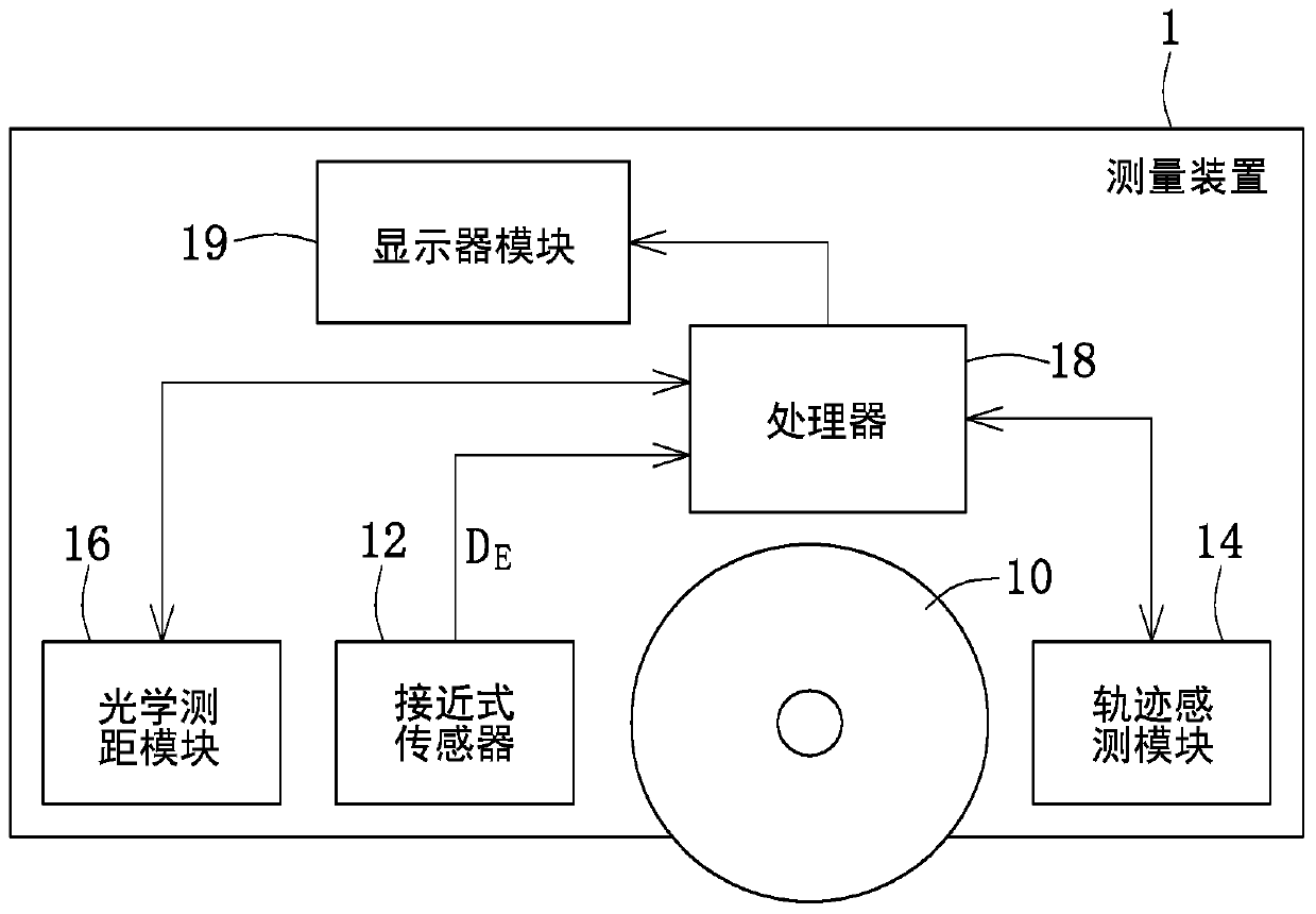
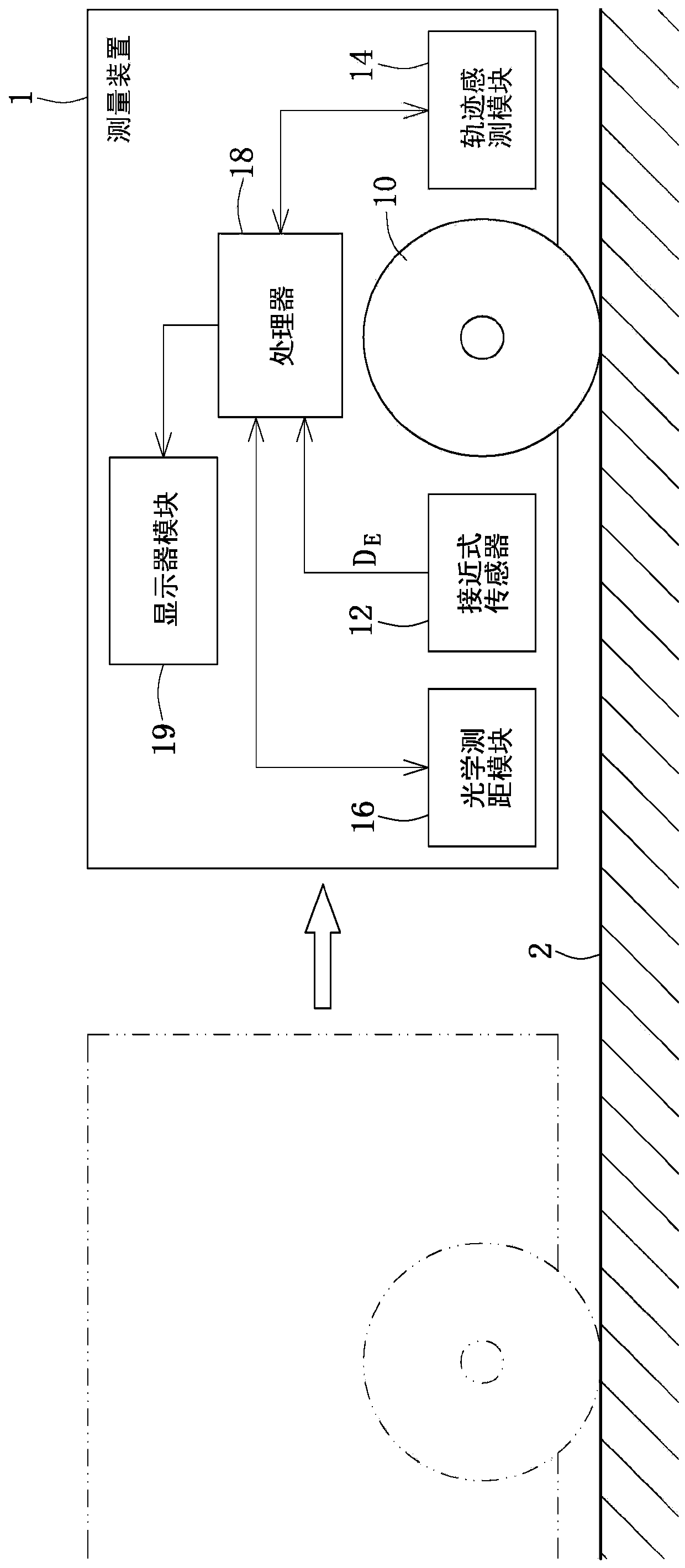
[0031] First, please also see figure 1 and figure 2 , figure 1 is a functional block diagram of the measuring device provided by the embodiment of the present invention, and figure 2 It is a schematic diagram of the operation process of the measuring device provided by the embodiment of the present invention. The measuring device 1 mainly includes a wheel 10 , at least one proximity sensor 12 , a track sensing module 14 , an optical distance measuring module 16 and a processor 18 . Wherein, the trajectory sensing module 14 , the optical distance measuring module 16 and...


PUM


Abstract

Embodiments of the present invention provide a measuring device and its operating method, a track sensing system and its track sensing method. The measuring device detects the distance change between the measuring device and an object through a built-in proximity sensor, and judges whether to turn on or off the trajectory sensing module and the optical ranging module, so that the present invention The measuring device can have an intelligent selectable operation function, thereby achieving the advantages of energy saving and power saving, and avoiding the interference caused by unnecessarily turned on sensors.

Description

technical field [0001] The present invention relates to a measuring device and its operating method, and in particular to a measuring device supporting optical distance measurement and track sensing and its operating method. Background technique [0002] In the prior art, a measuring device that only supports the principle of optical distance measurement emits detection light to the object to be measured, and by receiving the detection light reflected from the object to be measured, it is calculated that the light travels between the measuring device and the object to be measured. The time of flight (TOF) of light can be used to calculate the distance between the measuring device and the object to be measured. [0003] However, the above optical distance measuring principle cannot calculate the surface length of the object to be measured according to the detection light reflected by the object to be measured. Therefore, if it is necessary to know the surface length of the o...

Claims


Application Information

Patent Timeline
Patent Type & Authority Patents(China)
IPC IPC(8): G06F3/0346
CPCG01B11/043G01C21/005
Inventor 张廷仰郭士维张彦闵
Owner PIXART IMAGING INC
Learn More