
Instrument mounting box of instrument supporting device

An installation box and support technology, applied in the field of instruments, can solve the problems of fixed installation position of the instrument, inconvenient instrument observation, inability to realize multi-angle adjustment of the instrument, etc., and achieve the effect of tightening installation

Inactive Publication Date: 2017-12-19
合肥英源新材料科技有限公司
View PDF3 Cites 0 Cited by
  • Summary
  • Abstract
  • Description
  • Claims
  • Application Information

AI Technical Summary

Problems solved by technology

[0004] The technical problem to be solved by the present invention is to provide an instrument supporter to solve the problem that the existing instruments usually have a fixed installation position and cannot realize multi-angle adjustment of the instrument, thus making it inconvenient to observe the instrument

Method used


Image

  • Instrument mounting box of instrument supporting device
  • Instrument mounting box of instrument supporting device

Examples


Embodiment 1

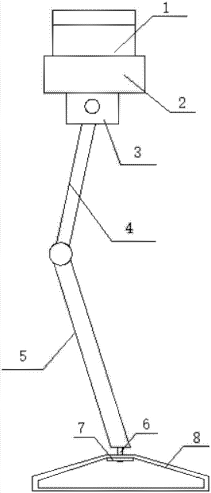
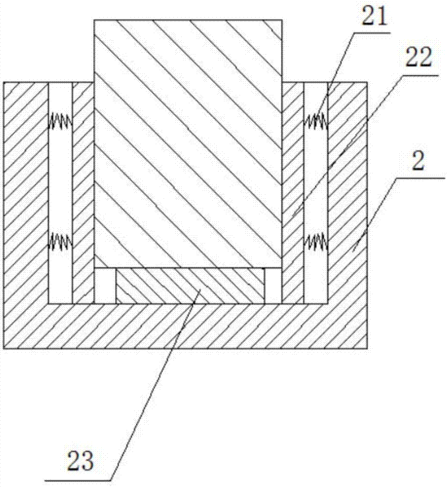
[0033] Such as Figure 1 to Figure 2 As shown, the present invention provides an instrument supporter, comprising: an instrument installation box 2, a bearing block 3, a first support rod 4, a second support rod 5, bolts 6, gaskets 7 and a base 8; the instrument installation box 2 is used to install the instrument 1; the bearing block 3 is arranged at the bottom of the instrument installation box 2; one end of the first support rod 4 is rotatably connected to the bearing block 3, and the other end of the first support rod 4 One end is rotationally connected with one end of the second support rod 5, the other end of the second support rod 5 is provided with the bolt 6; the top of the base 8 is provided with a through hole, and the bolt 6 passes through the through hole. One end of the bolt 6 passing through the through hole is threadedly connected with the gasket 7; the instrument installation box 2 is provided with a spring 21 opposite to the two inner walls, and the deformati...

Embodiment 2

[0036] A method for manufacturing an instrument installation box of an instrument supporter, the steps are as follows:

[0037] ①. The structure and molding of the instrument installation box

[0038] The opposite inner walls of the instrument installation box are provided with springs, and the deformation direction of the spring is perpendicular to the side wall of the instrument installation box; the spring is provided with an extrusion plate, which is parallel to the side wall of the instrument installation box, and the extrusion plate It is used to install the instrument; there is a pad at the bottom of the instrument installation box;

[0039] The material of the instrument installation box is stainless steel, which is welded by stainless steel plates; the material of the extrusion plate is foam rubber sponge; the material of the spring is carbon spring steel wire; the material of the pad is foam rubber sponge;

[0040] ②. Pretreatment of extruded plates and pads

[004...


PUM


Abstract

The invention relates to the technical field of instruments, in particular to an instrument mounting box of an instrument supporting device. Springs are arranged on the two opposite inner walls of the instrument mounting box, and the deformation directions of the springs are perpendicular to the side walls of the instrument mounting box; squeezing boards are arranged on the springs and are parallel to the side walls of the instrument mounting box; the space between the squeezing boards is used for mounting an instrument; and a cushion block is arranged at the bottom of the instrument mounting box. According to the instrument mounting box of the instrument supporting device and a manufacturing method of the instrument mounting box of the instrument supporting device, a product enables the instrument to be mounted in a fastened mode; and meanwhile, through the squeezing boards and the cushion block which are made of special materials and processing techniques, the surface of the instrument can be protected to a certain extent, and scratches are avoided.

Description

technical field [0001] The invention relates to the technical field of instruments, in particular to an instrument installation box of an instrument support. Background technique [0002] Meters are widely used in various industries. Existing meters are usually installed in a fixed position, and multi-angle adjustment of the meter cannot be realized, thereby making it inconvenient to observe the meter. [0003] At the same time, some of the existing instrument fixing structures are likely to cause relatively large scratches on the surface of the instrument because of the characteristics of the fixing structure material. Contents of the invention [0004] The technical problem to be solved by the present invention is to provide an instrument supporter to solve the problem that the existing instrument usually has a fixed installation position and cannot realize multi-angle adjustment of the instrument, thus making it inconvenient to observe the instrument. At the same time...

Claims


Application Information

Patent Timeline
Patent Type & Authority Applications(China)
IPC IPC(8): G12B9/08G12B9/06
CPCG12B9/08G12B9/06
Inventor 邬家银
Owner 合肥英源新材料科技有限公司
Learn More