Antenna and electronic equipment

A technology for electronic equipment and antennas, applied in antenna support/mounting devices, independent non-interactive antenna combinations, radiation unit covers, etc., can solve the problems of increasing manufacturing costs, unfavorable miniaturization and improvement of electronic equipment, and high manufacturing costs and selling prices. problems, to achieve the effect of reducing purchases

Inactive Publication Date: 2017-12-19
HEFEI LCFC INFORMATION TECH
View PDF4 Cites 5 Cited by
  • Summary
  • Abstract
  • Description
  • Claims
  • Application Information

AI Technical Summary

Problems solved by technology

[0003] However, in the existing technology, in order to meet the design requirements of the full frequency band or be able to cover more frequency bands, the size of the antenna needs to become larger, for example, generally reaching 50*10*1mm, and the requirements for the quiet zone are also higher ; This causes the antenna to take up more space in the housing of the electronic device, which is not conducive to the miniaturization and improvement of the electronic device. In some solutions, the antenna is directly integrated with the housing of the electronic device, although it can save Space will also bring other problems; in addition, setting up antennas that can cover multiple frequency bands in the same electronic device also increases the difficulty of antenna debugging and increases manufacturing costs
In addition, under normal circumstances, users only need to use a few commonly used frequency bands in the process of using electronic equipment, and other frequency bands are mostly idle, and may not be used until the electronic equipment is scrapped. Electronics that can cover more frequency bands Both the manufacturing cost and the selling price of the equipment are high, and these costs ultimately need to be paid by consumers. The requirements of multiple frequency bands will not bring about many of the above-mentioned problems

Method used


Image

  • Antenna and electronic equipment
  • Antenna and electronic equipment
  • Antenna and electronic equipment

Examples


Embodiment approach

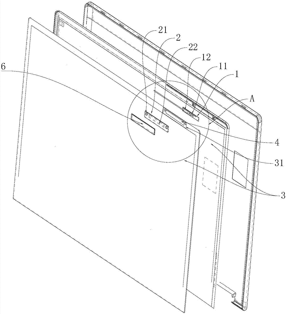
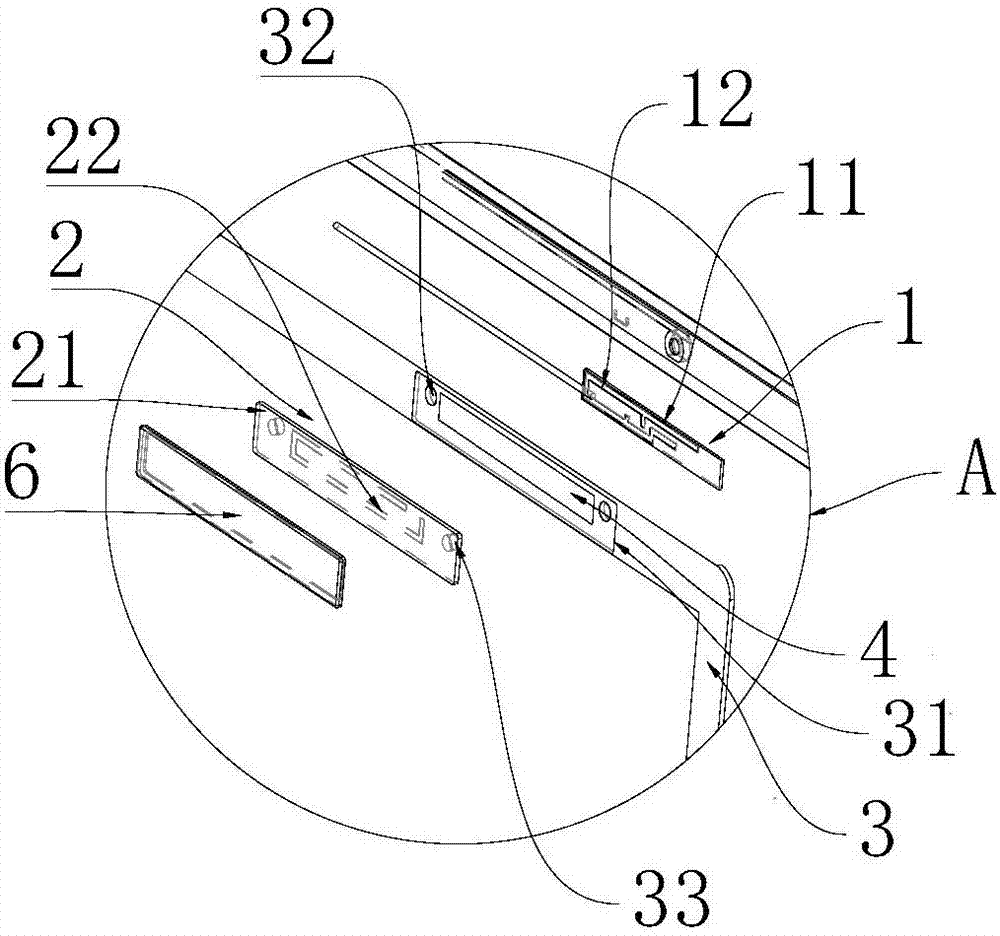
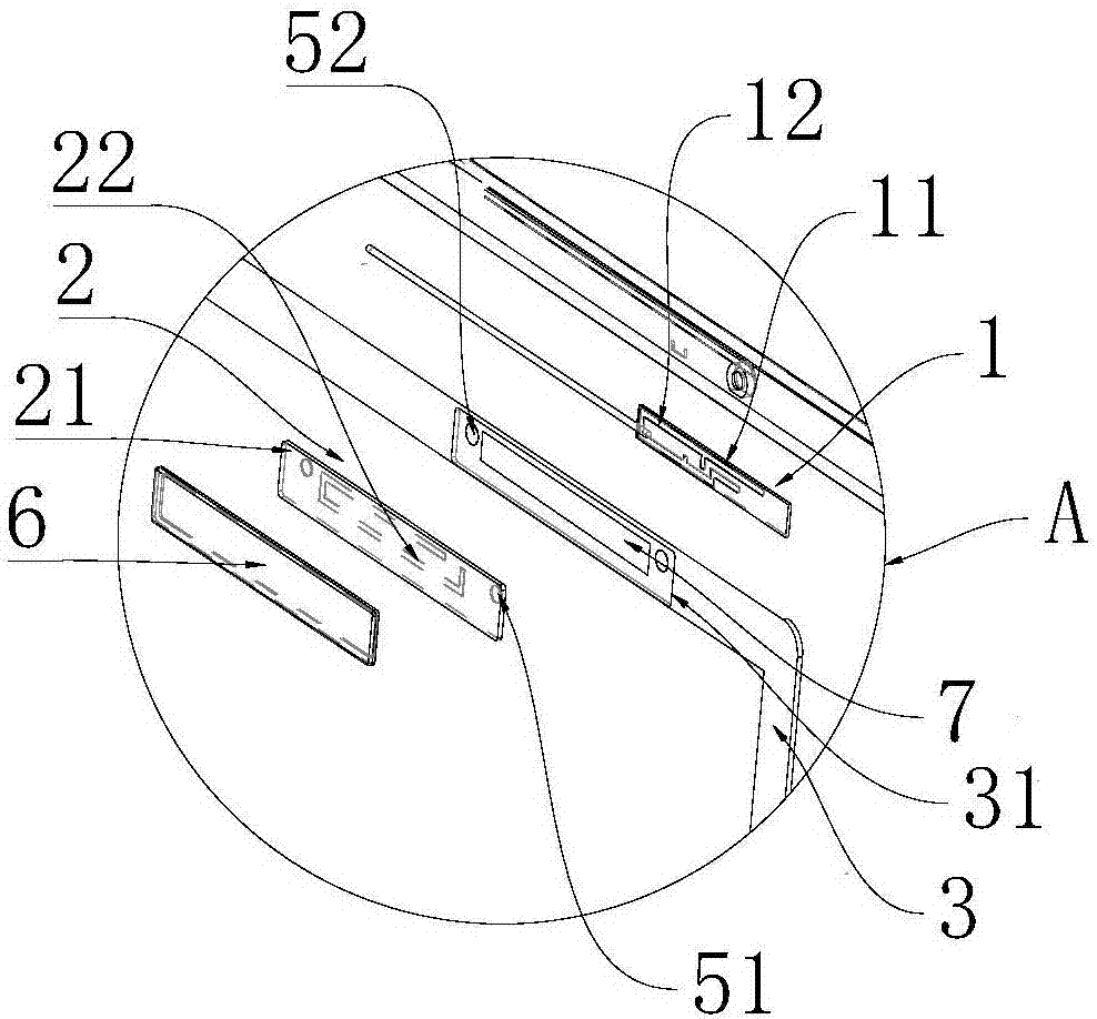
[0030] In this embodiment, the electronic device feeds the first antenna unit 1 during operation, and the current radiates to the second antenna unit 2 through coupling, so that the electronic device can simultaneously cover the first antenna unit 1 and the second antenna unit 2 The frequency band realizes the function of increasing the basic frequency band of the electronic device. For example, the first antenna unit 1 set in the shell 3 of the electronic device can only cover the 4G frequency band of TD-LTE of China Mobile, and is set on the outer wall of the shell 3 of the electronic device The second antenna unit 2 can at least cover the 4G frequency band of China Unicom's FDD-LTE, and through the coupling of the first antenna unit 1 and the second antenna unit 2, the electronic device can cover these two frequency bands at the same time. Specifically, the first The frequency bands that can be covered by the first antenna unit 1 and the second antenna unit 2 can be set free...


PUM


Abstract

The invention provides an antenna and electronic equipment. The antenna is applied to the electronic equipment. The electronic equipment comprises a shell, wherein the antenna comprises a first antenna unit and a second antenna unit; the first antenna unit is arranged on the inner surface of the shell, and the frequency range of the first antenna unit is configured to at least comprise a first frequency band; and the second antenna unit is arranged on the outer surface of the shell, and the frequency range of the second antenna unit is configured to at least comprise a second frequency band which is different from the first frequency band, wherein the second antenna unit and the first antenna unit penetrate through the shell to form coupling to enable the electronic equipment to receive signals at the first frequency band and the second frequency band at the same time. By virtue of the antenna and the electronic equipment, the frequency band coverage of the electronic equipment can be selected according to needs, so that miniaturization and ultra-thin appearance of the electronic equipment can be facilitated; and a user can buy the antenna which can cover different frequency bands and is used as external connection equipment in a targeted manner according to needs, without purchasing the electronic equipment which can cover all frequency bands, thereby lowering electronic equipment purchasing cost of consumers.

Description

technical field [0001] The invention relates to the field of wireless communication, in particular to an antenna and electronic equipment. Background technique [0002] It is known that the antenna is a conversion device between the space radio wave signal and the AC current signal in the circuit. The space radio wave signal is transmitted to the circuit through the antenna; the AC current signal in the circuit is finally transmitted to the space through the antenna. In recent years, With the continuous introduction of various new intelligent communication terminal electronic devices, the design of antennas that provide communication functions for electronic devices has become more important. Electronics for antennas that cover more frequency bands to respond to various needs. [0003] However, in the existing technology, in order to meet the design requirements of the full frequency band or be able to cover more frequency bands, the size of the antenna needs to become larg...

Claims


Application Information

Patent Timeline
Patent Type & Authority Applications(China)
IPC IPC(8): H01Q1/42H01Q1/22H01Q21/28
CPCH01Q1/22H01Q1/42H01Q21/28
Inventor 汪建安梁书芳吴枝强
Owner HEFEI LCFC INFORMATION TECH
Why Eureka
Try Eureka