Traffic cone placement vehicle

A technology of traffic cones and trucks, which is applied to traffic signals, roads, road signs, etc., and can solve the problem of inconvenient placement of traffic cones

Active Publication Date: 2017-12-22
山东正晨科技股份有限公司
View PDF5 Cites 3 Cited by
  • Summary
  • Abstract
  • Description
  • Claims
  • Application Information

AI Technical Summary

Problems solved by technology

[0003] In order to achieve the purpose of the above invention, and aiming at the problem of inconve

Method used


Image

  • Traffic cone placement vehicle
  • Traffic cone placement vehicle
  • Traffic cone placement vehicle

Examples


Embodiment 1

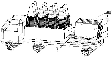
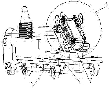
[0026] see Figure 1 to Figure 3 , the present invention provides a vehicle for placing traffic cones, comprising a truck body, and a truck body arranged at the rear of the truck body, and a traffic cone placement unit 1 is arranged on the rear side of the truck body;

[0027] The traffic cone placement unit 1 includes a base 2 and a traffic cone placement mechanism 4, the base 2 is connected to the rear of the truck body through rails, the base 2 is provided with a telescopic push rod 3, and one end of the telescopic push rod 3 is fixed to the base 2 connected, and the other end is fixedly connected to the lower surface of the traffic cone placement mechanism 4;

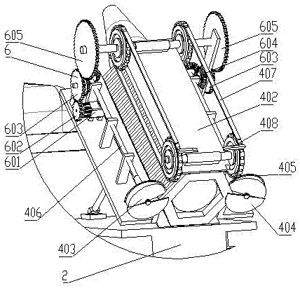
[0028] The traffic cone input port is reserved on the front side of the traffic cone placement mechanism 4, and the traffic cone exit is set on the rear side. The rear lower edge of the traffic cone placement mechanism 4 is hinged with the rear edge of the base 2; the traffic cone placement mechanism 4 The upper su...

Embodiment 2

[0043] On the basis of Embodiment 1, the rear side of the traffic cone channel 402 can be provided with a slide rail, and the slide rail extends to a position closer to the ground, and the auxiliary traffic cone slides down along the slide rail.

Embodiment 3

[0045] On the basis of Embodiment 1, a vibration mechanism is added between the traffic cone placement mechanism 4 and the telescopic push rod 3. The vibration mechanism includes a base plate and a vibration motor, and the lower side of the base plate is fixedly connected with one end of the telescopic push rod 3. The upper part is hinged to the rear side edge of the traffic cone placement mechanism 4, and the lower part is hinged to the rear side edge of the bottom platform 2. A spring is arranged between the front part of the bottom plate and the lower side of the traffic cone placement mechanism 4, and the traffic cone placement mechanism 4 A vibration motor is arranged inside, or an eccentric wheel is added on the output shaft of its original motor.


PUM


Abstract

The invention discloses a traffic cone placement vehicle, and relates to the field of road traffic equipment. According to the technical scheme, the traffic cone placement vehicle comprises a truck body and a vehicle hopper arranged on the rear portion of the truck body, and a traffic cone placement unit is arranged on the rear side of the vehicle hopper; the traffic cone placement unit comprises a bottom table and a traffic cone placement mechanism, the bottom table is connected with the rear portion of the truck body through a rail, and a telescopic push rod is arranged on the bottom table; one end of the telescopic push rod is fixedly connected with the bottom table, and the other end of the telescopic push rod is fixedly connected with the lower surface of the traffic cone placement mechanism; a solar charging panel is arranged on the upper surface of a shell of the traffic cone placement mechanism, and the solar charging panel supplies power to the traffic cone placement mechanism through a storage battery. The traffic cone placement vehicle has the advantages that a traffic cone structure used by the device is basically similar to an existing traffic cone and is simple and easy to manufacture; the traffic cone placement unit and a truck are assembled together through a vehicle-mounted structure, and people only need to add traffic cones into the traffic cone placement unit during placement to automatically place the traffic cones in the advancing process of the vehicle.

Description

technical field [0001] The invention relates to the field of road traffic equipment, in particular to a vehicle for placing traffic cones. Background technique [0002] Expressway is an important way of intercity traffic. When it needs to be repaired, in order to ensure that it still has a certain traffic capacity, it usually occupies a part of the adjacent reverse lane. In order to temporarily separate the lanes, it usually needs to be placed A large number of traffic cones are used to separate lanes by placing traffic cones at long distances. However, there is no device for effectively placing traffic cones at present, and the entire journey is very long by manually placing them. Contents of the invention [0003] In order to achieve the purpose of the above invention, and aiming at the problem of inconvenient placing of traffic cones, the present invention provides a vehicle for placing traffic cones. [0004] The technical solution is to separate and place the superi...

Claims


Application Information

Patent Timeline
IPC IPC(8): E01F9/70
CPCE01F9/70
Inventor 高鹤
Owner 山东正晨科技股份有限公司
Why Eureka
Try Eureka