Gear-rack driving type shaftless fan

A rack-and-pinion, driven technology, used in machines/engines, liquid fuel engines, axial flow pumps, etc. Large workable area, saving flow space, improving efficiency and noise performance

Inactive Publication Date: 2017-12-22
NORTHWESTERN POLYTECHNICAL UNIV +1
View PDF5 Cites 8 Cited by
  • Summary
  • Abstract
  • Description
  • Claims
  • Application Information

AI Technical Summary

Problems solved by technology

[0002] At present, the known fans are all driven by the central shaft to rotate the hub, and then the hub drives the blades to rotate. The existence of the hub occupies a large circulation space. Therefore, in order to ensure that the fan has a sufficient flow area when working, the blades The outer diameter of the fan is usually designed to be larger. At the same time, the increase in the outer diameter of the blade causes an increase in the linear velocity of the tip, which eventually leads to an increase in noise; there are often boundary layer separation and secondary flow at the connection between the hub and th

Method used


Image

  • Gear-rack driving type shaftless fan
  • Gear-rack driving type shaftless fan
  • Gear-rack driving type shaftless fan

Examples


Embodiment Construction

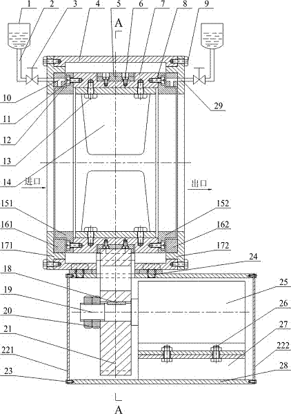
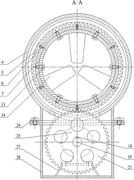
[0033] Such as Figure 1 to Figure 8 The rack and pinion driven shaftless fan shown includes the host part and the motor drive part;

[0034] The host part includes stator parts, rotor parts and lubricating devices;

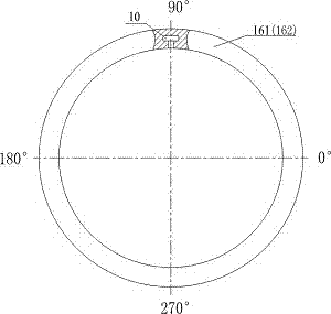
[0035] The stator component includes a front end cover 171, an inlet sliding bearing 161, an air cylinder 4, an outlet sliding bearing 162, and a rear end cover 172. The air cylinder 4 is a cylindrical structure with shoulders arranged on the inside of both ends, and a rectangular unfolded surface is arranged below it. The window is provided with a vertical plate around the window, one end of the vertical plate is welded on the fan cylinder 4 along the rectangular window, and the other end is provided with a rectangular flange, and the rectangular flange is provided with a plurality of through holes, the front cover 171 and the rear The end cover 172 is provided with a spigot and an oil guide hole 29, and the outer diameter of the spigot is equal to the inner di...


PUM


Abstract

The invention particularly relates to a gear-rack driving type shaftless fan which comprises a main engine part and a motor transmission part. The main engine part comprises a stator component, a rotor component and a lubricating device. The stator component comprises a front end cover 171, an inlet sliding bearing 161, an air barrel 4, an outlet sliding bearing 162 and a rear end cover 172. The rotor component comprises an inlet journal 151, a hub 7, an arc-shaped rack 5, blades 14 and an outlet journal 152. The lubricating device comprises oil cups 1, oil guiding pipes 2 and throttling valves 3. The motor transmission part comprises a base 28, a motor support 27, a motor 25, a motor shaft 19, a key 18, a round nut 20, a gear 21, a base front cover plate 221 and a base rear cover plate 222. According to the gear-rack driving type shaftless fan, by adopting the mode that the gear is engaged with the rack, the rotor component is driven to rotate from the rim, the flowing space occupied by a traditional fan hub disc is omitted, the working area of the blades 14 is increased, meanwhile, flowing in a runner is more uniform and reasonable, and the efficiency and noise performance are improved easily.

Description

technical field [0001] The invention relates to the technical field of fans, in particular to a rack and pinion driven shaftless fan. Background technique [0002] At present, the known fans are all driven by the central shaft to rotate the hub, and then the hub drives the blades to rotate. The existence of the hub occupies a large circulation space. Therefore, in order to ensure that the fan has a sufficient flow area when working, the blades The outer diameter of the fan is usually designed to be larger. At the same time, the increase in the outer diameter of the blade causes an increase in the linear velocity of the tip, which eventually leads to an increase in noise; there are often boundary layer separation and secondary flow at the connection between the hub and the blade of a traditional fan. The flow condition is poor, which affects the energy conversion effect and reduces the efficiency of the fan; in order to prevent the blade tip from scratching the fan duct, ther...

Claims


Application Information

Patent Timeline
IPC IPC(8): F04D25/06F04D29/52F04D29/32F04D29/38F04D29/063F04D29/66F04D29/056H02K7/116H02K7/14
CPCH02K7/116H02K7/14F04D25/06F04D29/056F04D29/063F04D29/325F04D29/388F04D29/522F04D29/663F04D29/668F04D25/02F04D19/002F04D29/057F04D29/326
Inventor 张森席德科李华星席晓东
Owner NORTHWESTERN POLYTECHNICAL UNIV
Why Eureka
Try Eureka