Wheel rim-driven shaftless fan

A rim drive and fan technology, which is applied to machines/engines, liquid fuel engines, mechanical equipment, etc., can solve the problems of reduced energy conversion efficiency, low energy conversion efficiency, increased aerodynamic noise, etc., to improve energy conversion efficiency and transportation. And the effect of easy installation and improved flow

Inactive Publication Date: 2017-12-12
NORTHWESTERN POLYTECHNICAL UNIV +1
View PDF6 Cites 11 Cited by
  • Summary
  • Abstract
  • Description
  • Claims
  • Application Information

AI Technical Summary

Problems solved by technology

[0002] At present, the known fans are connected to the hub through the motor shaft to drive the impeller to rotate. Due to the existence of the hub, in order to ensure a sufficient flow area, the outer diameter of the blade must be designed to be relatively large; at the same time, in order to ensure that the blade has sufficient strength, The root section airfoil chord and thickness of the blade must be designed to be larger, but in the case of the same airfoil chord, the output force of the blade increases with the increase of the radius, that is, for a fixed chord length When the airfoil section is located at the blade tip, its output force is much greater than that at the blade root, which causes a waste of material; due to the influence of secondary flow and boundary layer, the flow at the blade root is poor , the energy conversion efficiency is low, and the existence of the hub has caused a large loss; there is a certain gap between the blade tip and the casing of the traditional fan, and there is a certain pressure difference between the pressure surface and the suction surface of the blade, which causes the blade tip Flow around not only disturbs the flow field, reduces energy conversion efficiency, but also increases aerodynamic noise

Method used


Image

  • Wheel rim-driven shaftless fan
  • Wheel rim-driven shaftless fan
  • Wheel rim-driven shaftless fan

Examples


Embodiment Construction

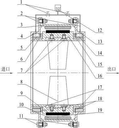
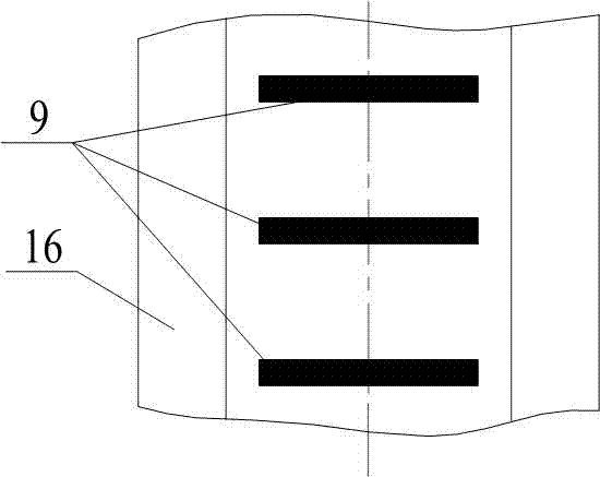
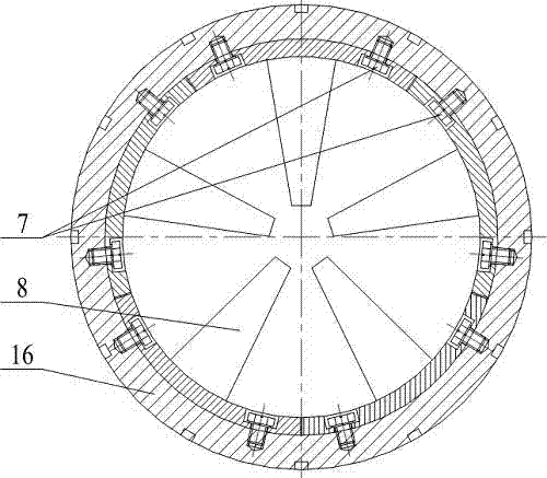
[0020] Such as Figure 1 to Figure 3 The rim-driven shaftless fan shown includes a stator part, a rotor part and a lubricating device; the stator part includes a front cover 4, an inlet side sliding bearing 5, an air duct 3, an armature 10, an outlet side sliding bearing 14 and a rear end The cover 13 and the air cylinder 3 are cylindrical structures, the two ends of the air cylinder 3 are provided with flanges, and the flanges are provided with a plurality of evenly distributed through holes, and the front end cover 4 and the rear end cover 13 are provided with stoppers. The outer diameter of the mouth is equal to the inner diameter of the air cylinder 3, and the front end cover 4 and the rear end cover 13 are also provided with a plurality of evenly distributed through holes, which are equal in diameter and number to the through holes on the flange of the air cylinder 3 , and the center line coincides, the front end cover 4 and the rear end cover 13 are installed on both end...


PUM


Abstract

The invention specifically relates to a wheel rim-driven shaftless fan. The wheel rim-driven shaftless fan comprises a stator component, a rotor component and a lubrication device, wherein the stator component comprises a front end cover 4, an inlet-side slide bearing 5, an air barrel 3, an armature 10, an outlet-side slide bearing 14 and a rear end cover 13, wherein the rotor component comprises an inlet-side shaft neck 6, a wheel hub 16, permanent magnets 9, blades 8 and an outlet-side shaft neck 15, the inlet-side shaft neck 6 and the outlet-side shaft neck 15 are both L-shaped and both installed on the wheel hub 16 in a manner of interference fit, a plurality of grooves are uniformly formed in the excircle surface of the wheel hub 16, and the permanent magnets 9 are inlaid in the grooves in the excircle surface of the wheel hub 16; a blade handle is arranged at the blade tip of each blade 8, each blade handle is an incurved tile, and all the tiles are spliced to just form the inner diameter of the wheel hub; and the lubrication device comprises an oil cup 12, a guide pipe 2 and an adjustment valve 1, one end of the guide pipe 2 is connected to the oil cup 12, and two outlets are formed in the other end of the guide pipe 2. According to the wheel rim-driven shaftless fan disclosed by the invention, a wheel hub needed for driving the central shaft of a traditional fan is avoided, the separation of secondary flow and a boundary layer at each blade root is reduced, and the flowing condition at each blade root is improved, so that the efficiency of the fan is increased; and moreover, a blade tip gap at each blade tip is avoided, so that detouring flow at each blade tip is avoided, a flow field structure is improved, energy conversion efficiency is increased, and a pneumatic noise is lowered.

Description

technical field [0001] The invention relates to the technical field of fans, in particular to a rim-driven shaftless fan. Background technique [0002] At present, the known fans are connected to the hub through the motor shaft to drive the impeller to rotate. Due to the existence of the hub, in order to ensure a sufficient flow area, the outer diameter of the blade must be designed to be relatively large; at the same time, in order to ensure that the blade has sufficient strength, The root section airfoil chord and thickness of the blade must be designed to be larger, but in the case of the same airfoil chord, the output force of the blade increases with the increase of the radius, that is, for a fixed chord length When the airfoil section is located at the blade tip, its output force is much greater than that at the blade root, which causes a waste of material; due to the influence of secondary flow and boundary layer, the flow at the blade root is poor , the energy conve...

Claims


Application Information

Patent Timeline
Patent Type & Authority Applications(China)
IPC IPC(8): F04D25/08F04D29/056F04D29/063F04D29/32F04D29/38F04D29/66
CPCF04D25/08F04D29/056F04D29/063F04D29/325F04D29/384F04D29/667
Inventor 张森符强席德科李华星
Owner NORTHWESTERN POLYTECHNICAL UNIV
Why Eureka
Try Eureka