Bracket for placing test tube
A bracket and test tube technology, which is applied in the directions of test tube brackets/clamps, laboratory utensils, chemical instruments and methods, etc., can solve the problems of occupying empty parts and inconvenience, and achieve the effect of convenient frequent movement.
Inactive Publication Date: 2017-12-26
李国云
View PDF0 Cites 0 Cited by
- Summary
- Abstract
- Description
- Claims
- Application Information
AI Technical Summary
Problems solved by technology
At present, when the test tubes commonly used in laboratories are moved or placed, they generally need to be moved by test tube clamps. The test tubes are placed on test tube racks at different operating positions. For some places where there may be only one or two reagents, but different reaction occasions are required, It is necessary to place test tube racks on every occasion to facilitate the placement of test tubes, which takes up a lot of empty parts and brings some inconvenience to experimental preparation and operation
Method used
View moreImage
Smart ImageViewing Examples

Examples
Embodiment 1
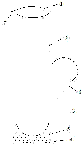
[0012] Such as figure 1 The shown bracket for placing test tubes includes a test tube 1 and a bracket 2. It is characterized in that the bracket 2 is a non-closed sleeve structure, and the bottom of the bracket 2 is provided with a weighted and stable layer 4, which is used to improve placement. Stability, the top of the stable layer 4 is provided with a buffer layer 5, the buffer layer 6 is cotton, used for buffering the test tube when placed, to avoid the rupture of the test tube caused by impact. The invention can conveniently move and place test tubes, and facilitates frequent movement of a small amount of reagents, and can even be used in a water bath or oil bath environment without supports.
Login to View More PUM
 Abstract
The invention discloses a bracket for placing a test tube, which includes a test tube and a bracket, and is characterized in that the bracket is a non-closed sleeve structure, and a weighted and stable layer is provided at the bottom of the bracket to improve the stability of placement. A buffer layer is arranged above the stable layer, and the buffer layer is cotton, which is used for buffering the test tube when it is placed, so as to avoid the rupture of the test tube caused by impact. The invention can conveniently move and place test tubes, and facilitates frequent movement of a small amount of reagents, and can even be used in a water bath or oil bath environment without supports.
Description
technical field [0001] The invention relates to the field of glass instrument devices commonly used in laboratories, in particular to a bracket for placing test tubes. Background technique [0002] The test tube is a kind of glass instrument commonly used in laboratories such as biochemistry. Its structure is simple, usually a flat glass tube with a round bottom, and the mouth of the tube is melted. At present, when the test tubes commonly used in laboratories are moved or placed, they generally need to be moved by test tube clamps. The test tubes are placed on test tube racks at different operating positions. For some places where there may be only one or two reagents, but different reaction occasions are required, Have to place the test tube rack on every occasion to facilitate the placement of the test tubes, take up a large amount of empty parts, and bring some inconvenience to the experimental preparation and operation. Contents of the invention [0003] In order to ...
Claims
Login to View More Application Information
Patent Timeline
 IPC IPC(8): B01L9/06
CPCB01L9/06B01L2300/0851
Inventor 李国云
Owner 李国云