
Pipe bagging mechanism

A technology for bagging and pipe material, applied in the field of pipe material bagging mechanism, can solve the problems of low pipe material packaging efficiency and qualified rate, unreliable film grasping, film falling off, etc., to facilitate high-speed film drawing operation, improve packaging efficiency and qualified rate, the effect of meeting production needs

Active Publication Date: 2019-07-09
ZHEJIANG WEIXING NEW BUILDING MATERIALS CO LTD
View PDF4 Cites 0 Cited by
  • Summary
  • Abstract
  • Description
  • Claims
  • Application Information

AI Technical Summary

Problems solved by technology

Existing PPR water supply pipes usually use a single bagging packaging process to pack a single pipe in a film bag. The existing pipe bagging mechanism realizes the bagging operation through film grabbing technology, and most of them use cylinder-type two-point grabbing. Taken, this technology is limited by the film thickness and film pulling speed of the film bag. It has a high success rate when the film thickness is large and the film pulling speed is low. It is easy to cause the film to be unreliably grasped, cause the film to fall off, and cause the film to be scratched or broken, which will eventually lead to low packaging efficiency and pass rate of the tube, which cannot meet the production demand.

Method used


Image

  • Pipe bagging mechanism
  • Pipe bagging mechanism
  • Pipe bagging mechanism

Examples


Embodiment Construction

[0029] The present invention will be further described below in conjunction with the accompanying drawings and specific embodiments, so that those skilled in the art can better understand the present invention and implement it, but the examples given are not intended to limit the present invention.

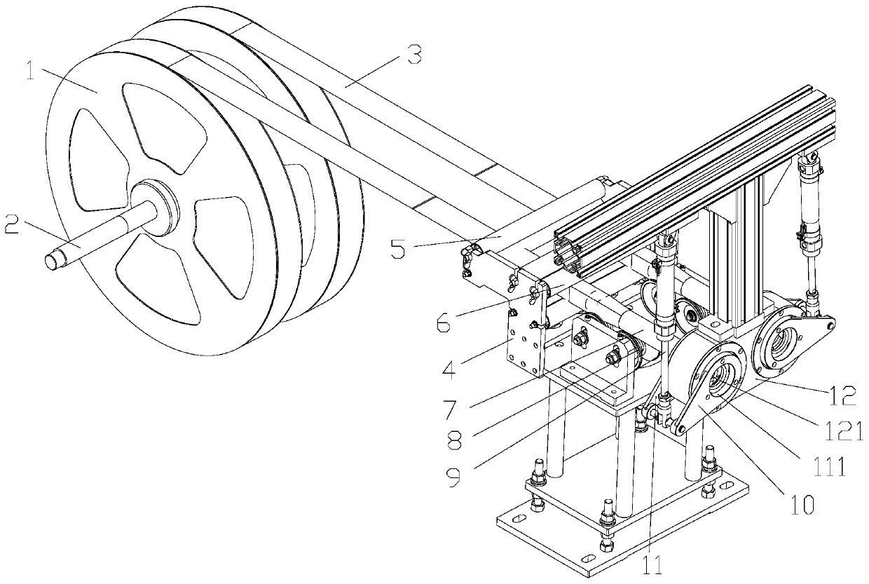
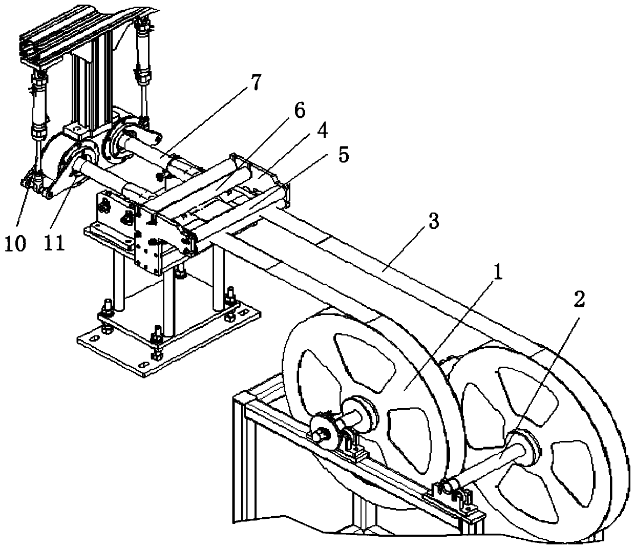
[0030] Such as figure 1 and figure 2 As shown, a pipe bagging mechanism includes a guiding mechanism, a forming mandrel 7 and a film clamping mechanism arranged in sequence;

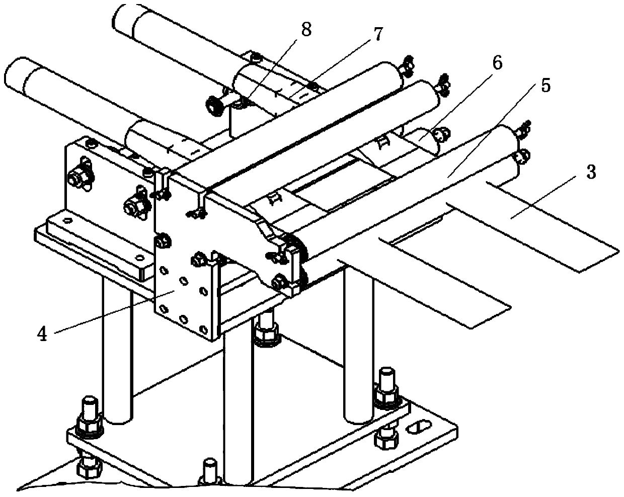
[0031] The guide mechanism includes a frame 4, on which a film guide roller and a mandrel positioning part 8 are arranged, and a forming mandrel 7 is arranged on the mandrel positioning part 8;

[0032] The film clamping mechanism includes a mounting plate 12 and a driving mechanism, and the mounting plate 12 is provided with an annular cavity 121 inside, such as Figure 9 As shown, one end surface of the mounting plate 12 is provided with a plurality of first track grooves 122, such as Figure 10 As sho...


PUM


Abstract

The invention discloses a pipe bagging mechanism which comprises a guiding mechanism, a forming mandrel and a thin film clamping mechanism which are sequentially arranged. The guiding mechanism comprises a rack; a thin film guiding roller and a mandrel positioning piece are arranged on the rack; and the forming mandrel is arranged on the mandrel positioning piece. The thin film clamping mechanism comprises a mounting plate and a driving mechanism; annular hole cavities are formed inside the mounting plate; a plurality of first track grooves and a plurality of second track grooves are formed in the two end faces of the mounting plate correspondingly, are formed in the radical direction of the annular hole cavities and communicate with the annular hole cavities; and first clamping pieces and second clamping pieces are slidably connected in the first track grooves and the second track grooves correspondingly and driven by the driving mechanism to move face to face or back to back. The surface of a thin film is clamped in a contact mode from the multiple directions, clamping is firmer, the forming output of the thin film is effectively guaranteed, and the thin film with the small thickness can be stably clamped and subjected to efficient film pulling operation under the high-speed condition.

Description

technical field [0001] The invention relates to the technical field of packaging, in particular to a pipe bagging mechanism. Background technique [0002] PPR pipe has the advantages of light weight, high strength, corrosion resistance, smooth inner wall, easy construction and maintenance, and long service life. It is widely used in building water supply and drainage, urban and rural water supply and drainage, city gas, industrial fluid transportation, agricultural irrigation and other construction industries. , municipal, industrial and agricultural fields. Existing PPR water supply pipes usually use a single bagging packaging process to pack a single pipe in a film bag. The existing pipe bagging mechanism realizes the bagging operation through film grabbing technology, and most of them use cylinder-type two-point grabbing. Taken, this technology is limited by the film thickness and film pulling speed of the film bag. It has a high success rate when the film thickness is l...

Claims


Application Information

Patent Timeline
Patent Type & Authority Patents(China)
IPC IPC(8): B65B41/14B65B5/04
CPCB65B5/045B65B41/14
Inventor 叶德园冯晓龙柳国斌
Owner ZHEJIANG WEIXING NEW BUILDING MATERIALS CO LTD
Learn More