An electric locking device for subway screen doors
What is Al technical title?
Al technical title is built by PatSnap Al team. It summarizes the technical point description of the patent document.
A technology for shielded doors and electric locks, applied to non-mechanical transmission-operated locks, building locks, buildings, etc., can solve problems such as difficulty in installation and debugging, lock pin adjustment and complex structure of anti-loosening functions, and achieve low cost and fixed connection High reliability, easy installation and debugging
Active Publication Date: 2022-06-24
NANJING KANGNI MECHANICAL & ELECTRICAL
View PDF6 Cites 0 Cited by
Summary
Abstract
Description
Claims
Application Information
AI Technical Summary
This helps you quickly interpret patents by identifying the three key elements:
Problems solved by technology
Method used
Benefits of technology
Problems solved by technology
[0003] The purpose of the present invention is to overcome the problems of the existing electric locking device for subway shield doors, the lock body and the lock pin are installed in different parts, the installation and debugging are somewhat difficult, and the lock pin adjustment and the anti-loosening function structure are complicated.
Method used
Image
Click on the blue label to locate the original text in one second.
Reading with bidirectional positioning of images and text.
Examples
Embodiment Construction
[0027] The present invention will be further described below with reference to the accompanying drawings. The following examples are only used to illustrate the technical solutions of the present invention more clearly, and cannot be used to limit the protection scope of the present invention.
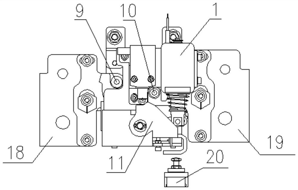
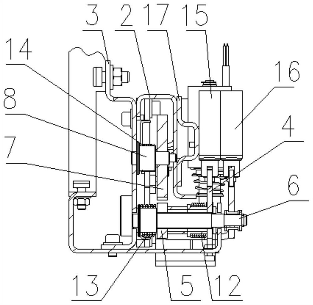
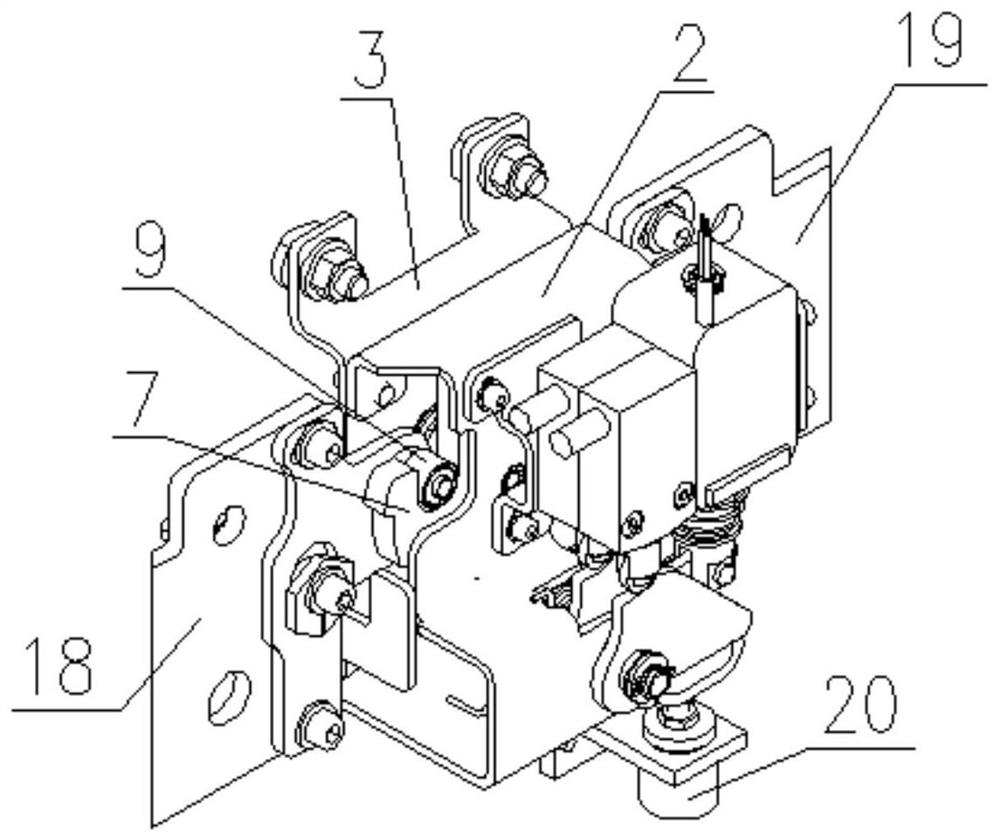
[0028] like Figure 1-Figure 4 As shown in the figure, the electric locking device for the subway screen door of the present invention is installed on the door machine guide rail of the subway screen door, and includes an electromagnet 1, a front bracket 2 of the lock body, a rear bracket 3 of the lock body, and a pawl dial 4 , pawl 5, pawl shaft 6, lock hook 7, lock hook shaft 8, left lock pin 9, right lock pin 10, manual unlocking mechanism 11, lock position detection switch 15, manual unlock detection switch 16 and switch bracket 17,
[0029] The left lock pin 9 and the right lock pin 10 are installed on the left carrying trolley 18 and the right carrying trolley 19 on the correspo...
PUM
Abstract
The invention discloses an electric locking device for a subway screen door, which is installed on the door machine guide rail of the subway screen door and includes an electromagnet, a front bracket of a lock body, a rear bracket of the lock body, a pawl dial, and a pawl , pawl rotating shaft, lock hook, lock hook rotating shaft, left lock pin, right lock pin, manual unlocking mechanism, lock in place detection switch, manual unlock detection switch and switch bracket, when the door leaf is automatically unlocked, the electromagnet is powered to do work Linear motion drives the pawl to rotate, the pawl on the pawl shaft rotates synchronously, the pawl disengages the lock hook, and the lock hook rotates under the action of the third torsion spring restoring force, so that the left lock pin and the right lock pin are separated from the lock. The left lock groove and right lock groove of the hook realize the automatic opening of the door leaf; when the door leaf is manually unlocked, the manual lock triggers the manual unlocking mechanism, triggers the manual unlock detection switch, and realizes the manual opening of the door leaf. The invention is convenient for maintenance, high in stability and has good application prospect.
Description
technical field [0001] The invention relates to an electric locking device for subway screen doors, belonging to the technical field of rail transit screen doors. Background technique [0002] With the rapid development of urban traffic, the demand for subway screen doors is also increasing. At present, the lock body of the electric locking device of the existing subway screen door is installed on the door machine beam, and the lock pin is installed on the door carrying frame of the door leaf, that is, the lock body and the lock pin are installed on different component positions. It is a bit difficult to debug and maintenance is inconvenient. Moreover, the lock pin adjustment and anti-loosening functions of the existing electric locking device have complex structures and high manufacturing costs. SUMMARY OF THE INVENTION [0003] The purpose of the present invention is to overcome the problems of the existing electric locking device of subway screen door, the lock body a...
Claims
Application Information
Patent Timeline
Application Date:The date an application was filed.
Publication Date:The date a patent or application was officially published.
First Publication Date:The earliest publication date of a patent with the same application number.
Issue Date:Publication date of the patent grant document.
PCT Entry Date:The Entry date of PCT National Phase.
Estimated Expiry Date:The statutory expiry date of a patent right according to the Patent Law, and it is the longest term of protection that the patent right can achieve without the termination of the patent right due to other reasons(Term extension factor has been taken into account ).
Invalid Date:Actual expiry date is based on effective date or publication date of legal transaction data of invalid patent.