Tunnel light-emitting device

A light-emitting device and tunnel technology, which is applied in the field of transportation, can solve problems such as blurred vision, and achieve the effects of increased flexibility, good warning effect, luminous effect and good warning effect

Inactive Publication Date: 2017-12-26
侯马市迪科特电子科技有限公司
View PDF0 Cites 2 Cited by
  • Summary
  • Abstract
  • Description
  • Claims
  • Application Information

AI Technical Summary

Problems solved by technology

However, even if warning road signs are marked, accidents often occur near expressway tunnels. Short-term blurred vision can easily lead to accidents

Method used


Image

  • Tunnel light-emitting device
  • Tunnel light-emitting device
  • Tunnel light-emitting device

Examples


Embodiment 1

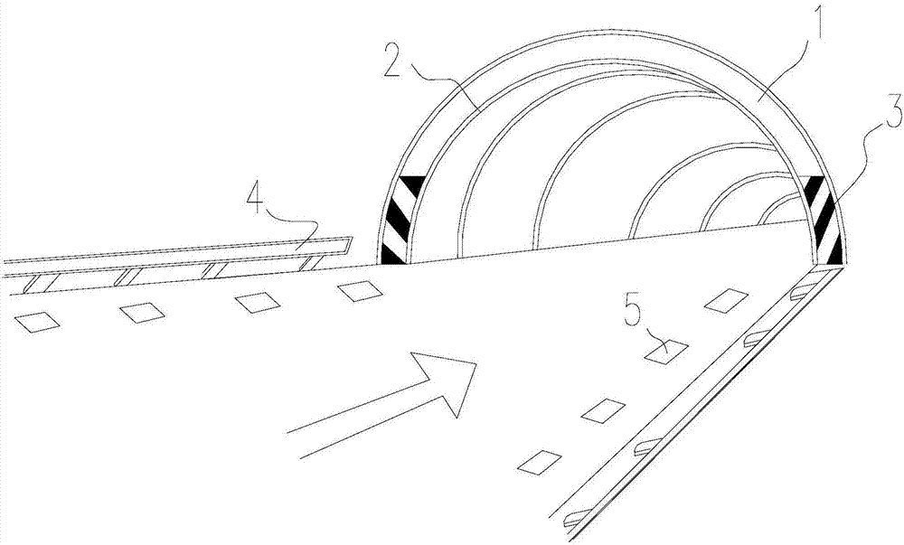
[0025] Such as figure 1 As shown, a tunnel lighting device includes a tunnel body 1 and a first lighting device 2. The first lighting device 2 is installed at the entrance of the tunnel according to the contour shape of the tunnel body 1 and evenly arranged at a certain distance along the tunnel body 1. direction and at the tunnel entrance of the tunnel body 1 is provided with a reflective film 3 .

[0026] The first light emitting device is one of an LED strip, an LED light source or an LED strip.

Embodiment 2

[0028] Such as figure 1 As shown, a tunnel light emitting device includes a tunnel body 1, a first light emitting device 2, corrugated plates 4 on both sides of the tunnel body 1, and reflective spikes 5 fixed on the road surface at the bottom of the tunnel body 1. The first light emitting device The device 2 is installed at the entrance of the tunnel according to the contour shape of the tunnel body 1 and evenly arranged at a certain distance along the direction of the tunnel body 1 and is provided with a reflective film 3 at the tunnel entrance of the tunnel body, and the corrugated plate 4 is also installed There is said first light emitting device 2 .

[0029] The first light emitting device is one of an LED strip, an LED light source or an LED strip.

[0030] The technical solutions of Embodiment 1 and Embodiment 2 can make the tunnel entrance and the corrugated plates on both sides near the tunnel entrance light up, and the reflective road studs on the ground can be mad...

Embodiment 3

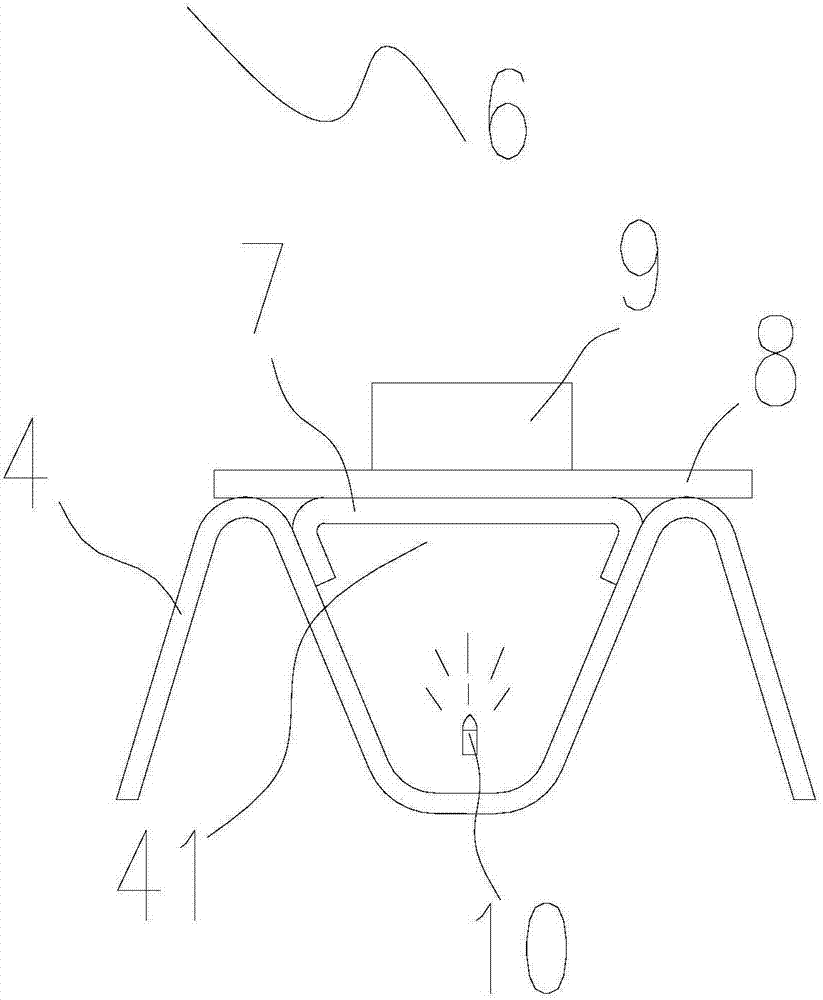
[0032] Such as figure 1 , 2 , 3, a tunnel light emitting device, including a tunnel body 1, a first light emitting device 2, corrugated plates 4 on both sides of the tunnel body 1, and reflective spikes 5 fixed on the road surface at the bottom of the tunnel body 1, the first A light-emitting device 2 is installed at the entrance of the tunnel according to the contour shape of the tunnel body 1 and is evenly arranged at a certain distance along the direction of the tunnel body 1 and is provided with a reflective film 3 at the tunnel entrance of the tunnel body 1, and the corrugated plate 4 is installed The second light emitting device 6 is provided.

[0033] The first light emitting device 2 is one of LED strips, LED light sources or LED strips.

[0034] The second light-emitting device 6 includes: a corrugated plate 4 , a light-transmitting plate 7 , a light-transmitting reflective film 8 , a reflective nail 9 and a luminous body 10 . The corrugated plate 4 is wave-shaped,...


PUM


Abstract

The invention relates to a tunnel lighting device, which includes a tunnel body and a first lighting device. The first lighting device is installed at the entrance of the tunnel and evenly arranged at a certain distance along the direction of the tunnel body. A reflective film is arranged at the tunnel entrance of the tunnel body. The device also includes corrugated plates on both sides of the tunnel body and reflective spikes fixed on the road surface at the lower part of the tunnel body. The corrugated plates are equipped with a first light emitting device or a second light emitting device. In the present invention, the first light-emitting device is installed at the entrance of the tunnel body and evenly arranged along the direction of the tunnel body, which ensures sufficient brightness for drivers entering the tunnel and greatly reduces the occurrence of accidents; the second light-emitting device The light emitted by the illuminant can be projected onto the light-transmitting reflective film and the reflective nail through the light-transmitting plate, so that it can be seen by driving vehicles and play a warning role.

Description

technical field [0001] The invention relates to the field of traffic, in particular to a tunnel lighting device. Background technique [0002] At present, with the rapid development of China's economy, considerable attention has been paid to the improvement of road traffic, which is reflected in the laying and popularization of expressways. Expressway is a high-grade kilometer, generally designed for a speed of 120 km / h or higher. The road surface includes four or more lanes, with a divider in the middle and guardrails on both sides. [0003] Since the vehicles on the expressway must keep running at a high speed, the safety of the road conditions is very important for the driving of the vehicles. Due to the complex environment of the expressway, there are often tunnels. Therefore, road signs are equipped on the guardrails near each tunnel or on the divider in the middle to remind drivers of vehicles to pay attention to road conditions. However, even if warning road signs a...

Claims


Application Information

Patent Timeline
Patent Type & Authority Applications(China)
IPC IPC(8): F21S9/02F21V19/00F21V7/00F21V13/00F21V17/10F21V23/00E01F9/553F21W131/101F21Y115/10F21Y115/30
CPCF21S9/02E01F9/553F21V7/00F21V13/00F21V17/10F21V19/001F21V23/02F21W2131/101F21Y2115/10F21Y2115/30
Inventor 祝新胜高华勇
Owner 侯马市迪科特电子科技有限公司
Why Eureka
Try Eureka