
Image processing device, image processing method, and recording medium recording image processing program

An image processing device and image processing technology, applied in image data processing, image enhancement, image analysis, etc., can solve problems such as blurring of small parts, image quality degradation, etc.

Active Publication Date: 2021-12-14
MITSUBISHI ELECTRIC CORP
View PDF11 Cites 0 Cited by
  • Summary
  • Abstract
  • Description
  • Claims
  • Application Information

AI Technical Summary

Problems solved by technology

[0002] When noise removal processing is performed on captured image data (hereinafter also referred to as "captured image") acquired by an imaging device, a small part of the subject in the captured image may be blurred, that is, the image quality may deteriorate.

Method used


Image

  • Image processing device, image processing method, and recording medium recording image processing program
  • Image processing device, image processing method, and recording medium recording image processing program
  • Image processing device, image processing method, and recording medium recording image processing program

Examples


Embodiment approach 1

[0027] "1-1" structure

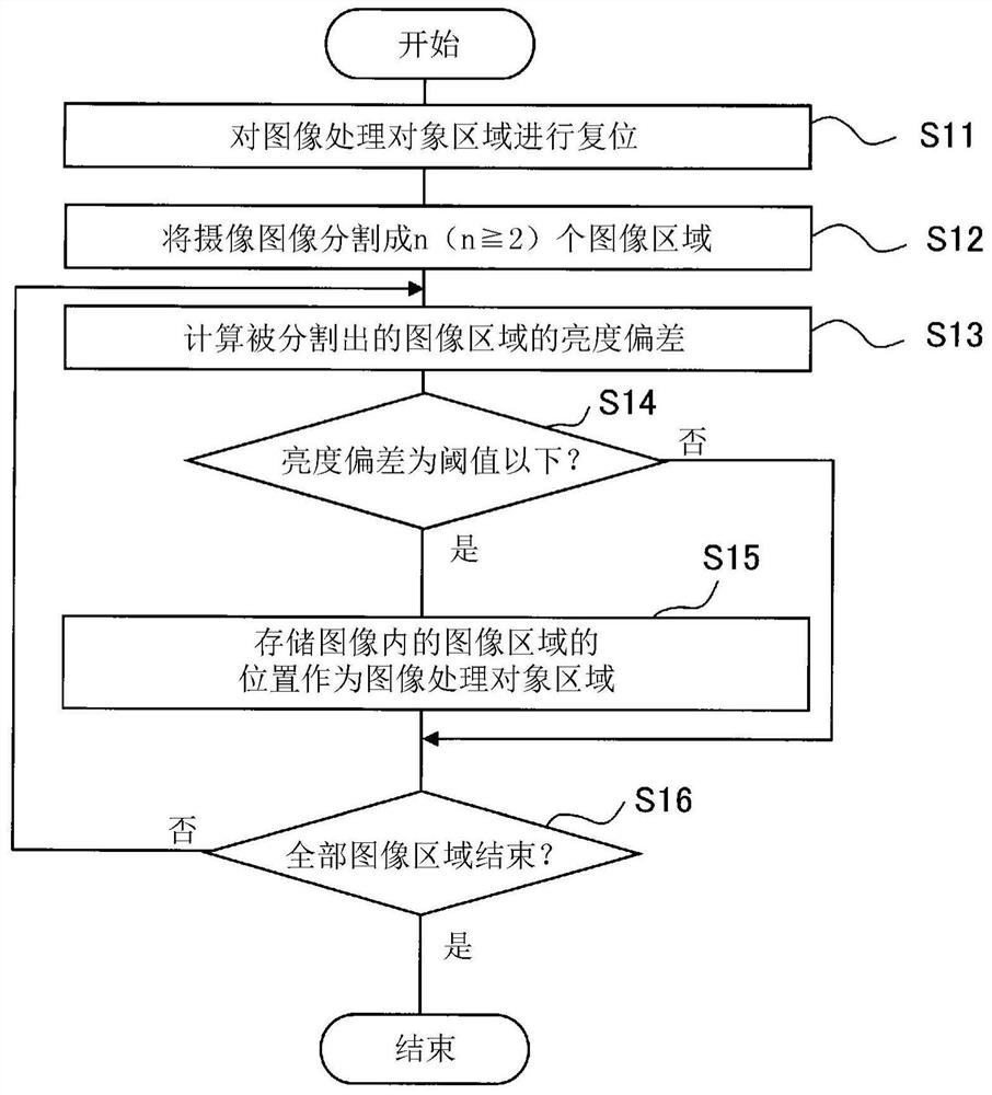
[0028] figure 1 It is a block diagram schematically showing the configuration of the image processing device 1 according to the first embodiment. figure 2 is roughly showing figure 1 A block diagram of the structure of the image area calculation unit 110. The image processing device 1 is a device capable of implementing the image processing method according to the first embodiment. The image processing device 1 may be a computer capable of executing the image processing program of the first embodiment.

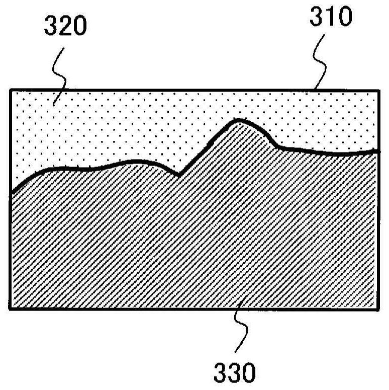
[0029] Such as figure 1 As shown, the image processing device 1 has a control unit 10 , a storage unit 20 , an input interface 30 and an output interface 40 . The control unit 10 has an image area calculation unit 110 , an image area readout unit 120 , a brightness determination unit 130 , a texture determination unit 140 , and an image processing unit 150 . Such as figure 2 As shown, the image area calculation unit 110 includes an image area ...

Embodiment approach 2

[0062] 《2-1》Structure

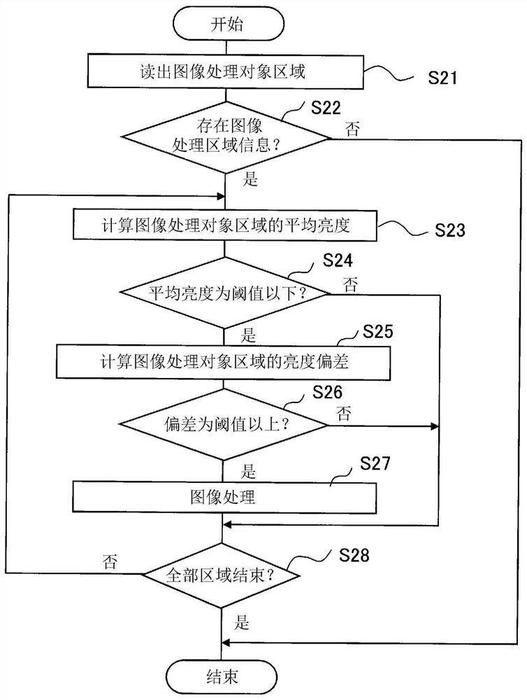
[0063] In Embodiment 1, the case where the subject to be monitored is located outside the image processing target area was described. In Embodiment 2, the operation of image processing (that is, noise correction processing) when a subject that is one of the monitoring targets is located in the image processing target area will be described.

[0064] Figure 7 It is a block diagram schematically showing the configuration of the image processing device 2 according to the second embodiment. exist Figure 7 in, right with figure 1 The structural elements shown are the same or the corresponding structural elements are labeled with figure 1 The numbers shown are the same as those shown. The image processing device 2 is a device capable of implementing the image processing method of the second embodiment. The image processing device 2 may be a computer capable of executing the image processing program of the second embodiment.

[0065] Such as Figure 7 ...


PUM


Abstract

An image processing device (1) for performing image processing for reducing noise of a captured image includes: an image area calculation unit (110) for measuring brightness variations representing a plurality of image areas based on a plurality of image areas obtained by dividing a captured image The first texture amount, according to the first texture amount, predetermines the image processing target area as the image processing target; the brightness determination part (130), it judges whether it is necessary to adjust the current image processing target area according to the brightness of the current captured image The image processing is performed on the captured image; the texture determination unit (140) calculates the second texture amount representing the brightness deviation of the image processing target area determined by the brightness determination unit to be subject to image processing, and determines whether to use the second texture amount according to the second texture amount image processing is performed on the image processing target area; and an image processing unit (150) that performs image processing on the image processing target area determined by the texture determination unit (140).

Description

technical field [0001] The present invention relates to an image processing device, an image processing method, and a recording medium in which an image processing program is recorded. Background technique [0002] When noise removal processing is performed on captured image data (hereinafter also referred to as “captured image”) acquired by an imaging device, a minute portion of a subject in the captured image may be blurred, that is, the image quality may deteriorate. As a countermeasure against this, a device has been proposed that determines whether noise removal processing is necessary based on the brightness of the captured image, and performs noise removal processing on the captured image when it is judged necessary (for example, refer to Patent Document 1). [0003] prior art literature [0004] patent documents [0005] Patent Document 1: Japanese Patent Laid-Open No. 2005-94087 Contents of the invention [0006] The problem to be solved by the invention [00...

Claims


Application Information

Patent Timeline
Patent Type & Authority Patents(China)
IPC IPC(8): H04N5/232G06T5/00H04N7/18
CPCH04N7/18G06T2207/20021G06T2207/10004G06T2207/20012G06T2207/30232G06T2207/30236H04N23/60G06T5/70G06T7/70G06T7/20G06T5/90
Inventor 古木一朗冈原浩平深泽司松村宽夫
Owner MITSUBISHI ELECTRIC CORP
Learn More