Terminal crimping devices and terminal crimping equipment

A bending device and terminal technology, applied in the direction of connection and connection by deformation, contact manufacturing, etc., can solve the problems of bending position error, low bending efficiency, reducing the quality of conductive terminals, etc., to ensure position accuracy and improve bending. The effect of reducing efficiency and ensuring surface quality

Active Publication Date: 2020-01-14
TYCO ELECTRONICS (SHANGHAI) CO LTD +1
View PDF6 Cites 5 Cited by
  • Summary
  • Abstract
  • Description
  • Claims
  • Application Information

AI Technical Summary

Problems solved by technology

However, manual bending can only bend one conductive terminal at a time, and cannot bend a row of conductive terminals at the same time, so the bending efficiency is very low
In addition, the accuracy of manual bending is difficult to guarantee, and there are often large errors in the bending position, which reduces the bending accuracy of the conductive terminal, which will make it difficult to correctly install the bent conductive terminal on the circuit board
In addition, during manual bending, workers need to use tools such as pliers to hold the conductive terminal, which will form scratches on the surface of the conductive terminal and reduce the quality of the conductive terminal

Method used


Image

  • Terminal crimping devices and terminal crimping equipment
  • Terminal crimping devices and terminal crimping equipment
  • Terminal crimping devices and terminal crimping equipment

Examples


Embodiment Construction

[0029] The technical solutions of the present invention will be further specifically described below through the embodiments and in conjunction with the accompanying drawings. In the specification, the same or similar reference numerals designate the same or similar components. The following description of the embodiments of the present invention with reference to the accompanying drawings is intended to explain the general inventive concept of the present invention, but should not be construed as a limitation of the present invention.

[0030] In addition, in the following detailed description, for purposes of explanation, numerous specific details are set forth in order to provide a comprehensive understanding of the embodiments of the present disclosure. It may be evident, however, that one or more embodiments may be practiced without these specific details. In other instances, well-known structures and devices are shown in diagrammatic form to simplify the drawings.

[0...


PUM


Abstract

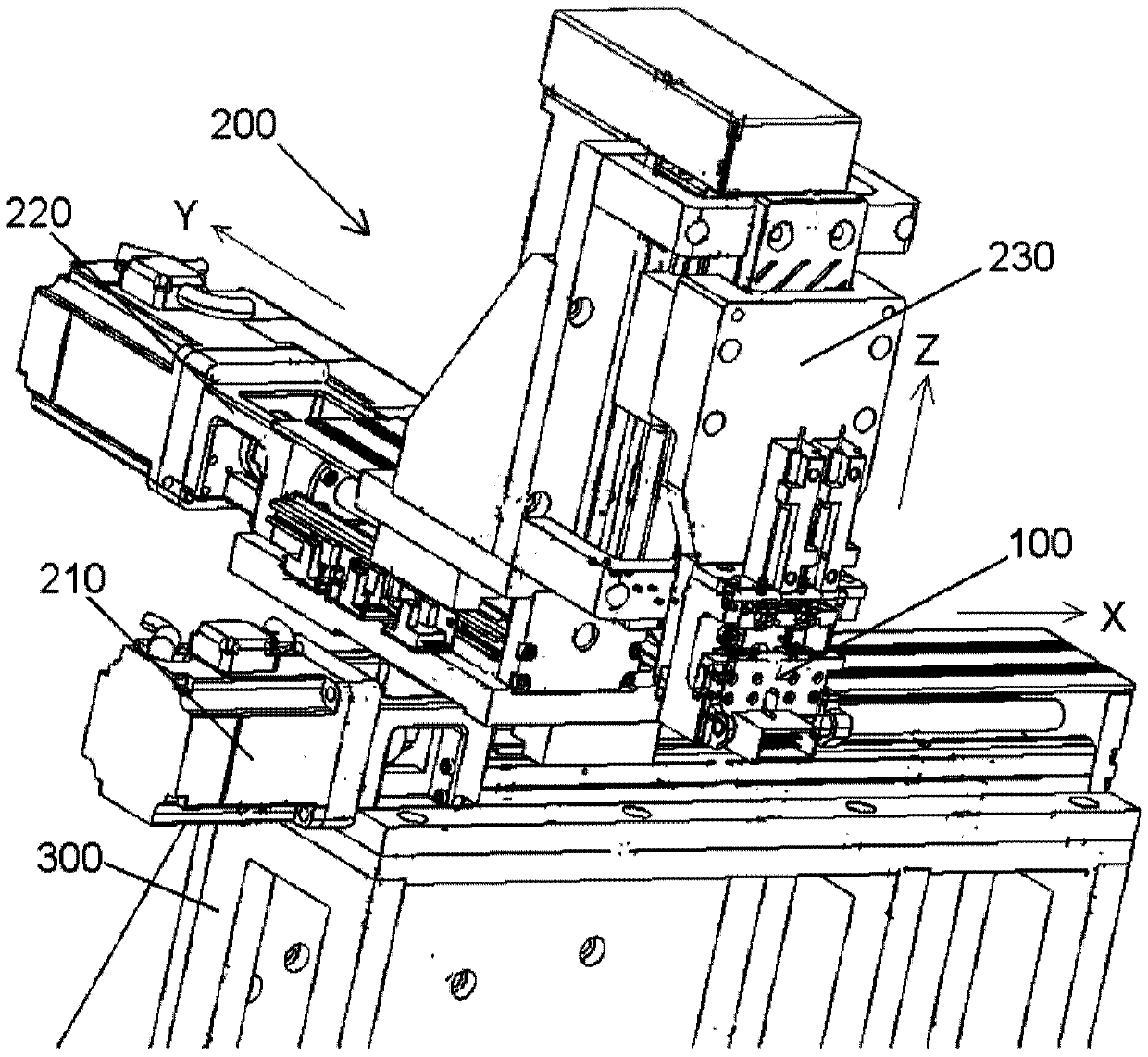
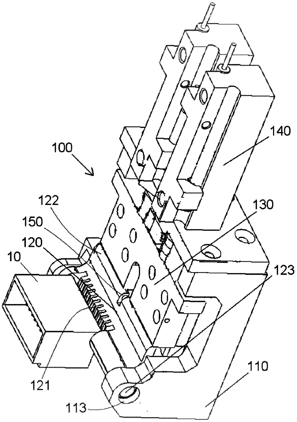
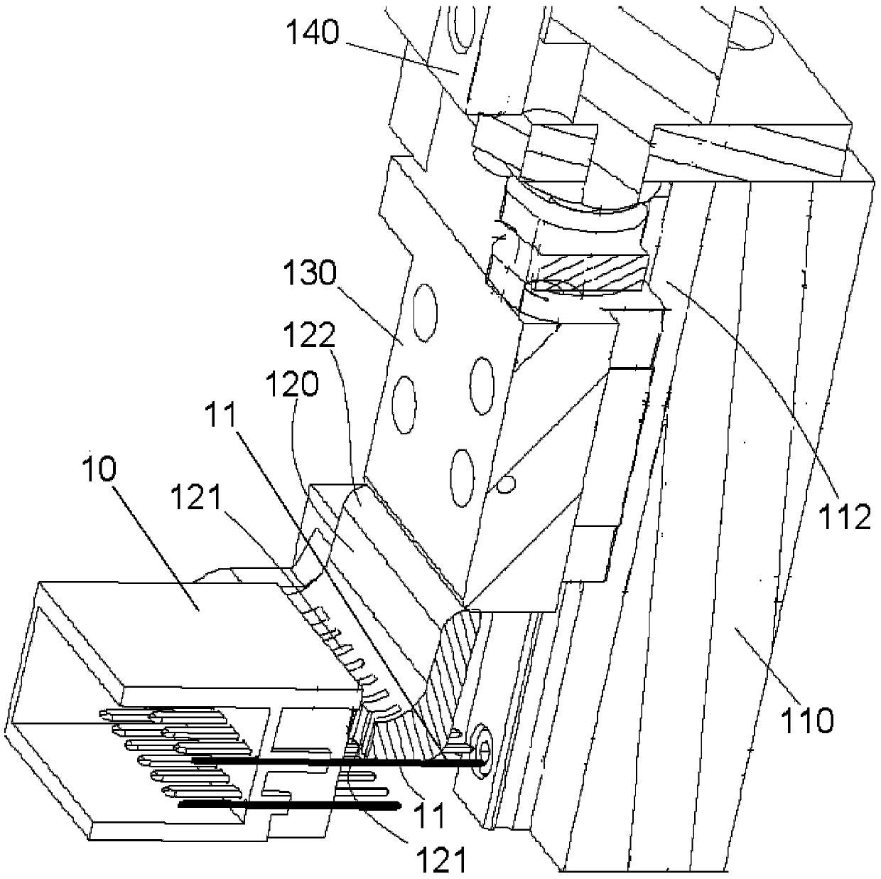
The invention discloses a terminal bending device, comprising: a frame; and a bending tool pivotally installed on the frame. A row of accommodating grooves is formed on the bottom surface of the bending tool, and the terminals to be bent are adapted to be accommodated and positioned in the corresponding accommodating grooves; when the bending tool is rotated, they are accommodated in the corresponding accommodating grooves The terminal is bent under the push of the bending tool. In the present invention, the bending of the terminal can be realized only by turning the bending tool, thereby improving the bending efficiency of the terminal. In addition, a row of terminals can be bent simultaneously by using the bending tool, thereby further improving the bending efficiency of the terminals. The mechanism of this bending device uses the frame as the body, which is respectively fixed on the frame or moves or rotates along the guide rail or rotating shaft fixed on the frame, and can reach any given position within the working range under the action of the driving mechanism. The working position, so as to realize the bending process of digital positioning.

Description

technical field [0001] The invention relates to a terminal bending device and terminal bending equipment comprising the terminal bending device. Background technique [0002] In the process of manufacturing the connector, sometimes it is necessary to bend the conductive terminal on the connector to a predetermined angle, for example, to bend 90 degrees. In the prior art, the conductive terminals are generally manually bent. However, manual bending can only bend one conductive terminal at a time, and cannot bend a row of conductive terminals at the same time, so the bending efficiency is very low. In addition, the accuracy of manual bending is difficult to guarantee, and there is often a large error in the bending position, which reduces the bending accuracy of the conductive terminal, which makes it difficult to correctly install the bent conductive terminal on the circuit board. In addition, during manual bending, workers need to use tools such as pliers to hold the condu...

Claims


Application Information

Patent Timeline
Patent Type & Authority Patents(China)
IPC IPC(8): H01R43/16
CPCH01R43/16B21D11/10B21D7/022B21D7/024B21F1/004H01R43/04
Inventor 代智勇胡绿海邓颖聪周磊刘云曾庆龙康伟
Owner TYCO ELECTRONICS (SHANGHAI) CO LTD
Why Eureka
Try Eureka