Moving-beam planer miller having chip discharging mechanism

A technology of gantry milling machine and moving beam, which is applied in the direction of milling machine, milling machine equipment, manufacturing tools, etc. It can solve the problems of not being able to clean quickly, not having a chip removal mechanism, and troublesome cleaning equipment debris, and achieves simple structure, fast and convenient cleaning, Ease of cleaning

Active Publication Date: 2017-12-29
ANHUI WANNAN ELECTRIC MACHINE
View PDF8 Cites 7 Cited by
  • Summary
  • Abstract
  • Description
  • Claims
  • Application Information

AI Technical Summary

Problems solved by technology

There are main rail brackets and vertically arranged left and right guide rails. The feature is that left and right wire racks are respectively fixed on the left and right guide rails. The steel wires are placed on the left and right wire racks. A heavy hammer is connected to each end respectively, the U-shaped brackets of the left wire frame and the right wire frame are respectively stuck on the left guide rail and the right guide rail, and the end of the bolt passes through the front end of the U-shaped bracket and is screwed on the spacer, and the The end is fixed with a gasket, the rear end of the U-shaped bracket is fixed with a positioning nail and a small shaft. The guide groove on the top matches the round-head guide flat key. The support column is set on the slider and locked by the locking screw. The depth micrometer fixing frame is located on the guide rail surface of the left guide rail and the right guide rail. Depth micrometer, however, the existing moving beam type gantry milling machine does not have a chip removal mechanism in use, it is troublesome to clean the sundries in the equipment, and it cannot be cleaned automatically and quickly, so it has certain limitations in use

Method used


Image

  • Moving-beam planer miller having chip discharging mechanism
  • Moving-beam planer miller having chip discharging mechanism
  • Moving-beam planer miller having chip discharging mechanism

Examples


Embodiment Construction

[0022] The following will clearly and completely describe the technical solutions in the embodiments of the present invention with reference to the accompanying drawings in the embodiments of the present invention. Obviously, the described embodiments are only some, not all, embodiments of the present invention.

[0023] Example.

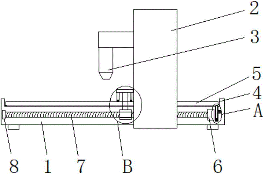
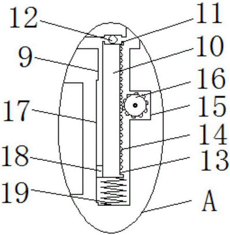
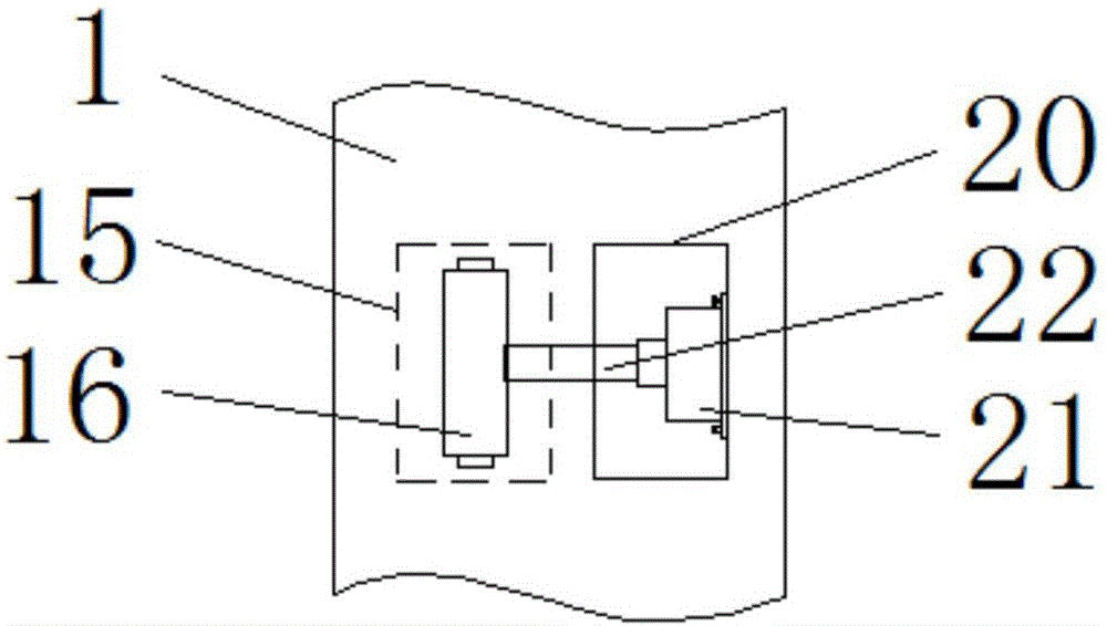
[0024] refer to Figure 1-5 , a moving beam type gantry milling machine with a chip removal mechanism, including a processing seat 1, a moving beam frame 2 is movably installed on both sides of the processing seat 1, and a cross bar is fixedly installed between the two moving beam frames 2, and the cross bar is far away from The bottoms of one end of the two moving beam frames 2 are fixedly equipped with a processing head 3, and the processing head 3 is located above the processing seat 1, and the top side of the processing seat 1 is provided with a processing groove 4 that is open on both sides. A movable plate 5 is movable, and the two sides of t...


PUM


Abstract

The invention discloses a moving-beam planer miller having a chip discharging mechanism. The moving-beam planer miller comprises a processing seat, a moving beam frame is movably mounted on each of two sides of the processing seat, a cross rod is fixedly mounted between the moving beam frames, a processing head is fixedly mounted at the bottom of one end, away from the moving beam frames, of the cross rod and positioned above the processing seat, a processing groove with openings on two sides is formed in the top side of the processing seat, a moving plate is movably mounted in the processing groove, two sides of the moving plate contact with inner walls on two sides of the processing groove respectively, a hinge is rotatably mounted on the moving plate positioned on one side away from the moving beam frames, and one end, away from the moving plate, of the hinge is rotatably mounted on the inner wall of the bottom side of the processing groove. The moving-beam planer miller is simple in structure and convenient to use, can bring convenience to controlling angle of the moving plate to quickly clean the moving plate through a cleaning plate and can automatically control the cleaning plate to clean the moving plate.

Description

technical field [0001] The invention relates to the technical field of a moving beam type gantry milling machine, in particular to a moving beam type gantry milling machine equipped with a chip removal mechanism. Background technique [0002] As we all know, with the development of machining technology and the needs of the machining industry, large-scale gantry machine tools that can process large-scale workpieces have emerged. In order to meet the processing needs of large-scale workpieces, beam-moving gantry milling machines are widely used. [0003] The patent application number 201110144901.4 discloses a column adjustment device for a moving beam type gantry milling machine, which belongs to the field of machine tools. There are main rail brackets and vertically arranged left and right guide rails. The feature is that left and right wire racks are respectively fixed on the left and right guide rails. The steel wires are placed on the left and right wire racks. A heavy h...

Claims


Application Information

Patent Timeline
Patent Type & Authority Applications(China)
IPC IPC(8): B23C1/00B23Q11/00
CPCB23C1/002B23Q11/0042
Inventor 郭文英
Owner ANHUI WANNAN ELECTRIC MACHINE
Why Eureka
Try Eureka