Automatic traction device

A traction device and automatic technology, applied in the direction of traction connectors, transportation and packaging, vehicle parts, etc., can solve the problems of difficult alignment connection, high labor intensity, poor safety, etc., to avoid misoperation, exquisite structure, and easy to operate Effect

Inactive Publication Date: 2017-12-29
SHANDONG DEFANG HYDRAULIC MACHINERY
View PDF7 Cites 2 Cited by
  • Summary
  • Abstract
  • Description
  • Claims
  • Application Information

AI Technical Summary

Problems solved by technology

[0002] At present, the connecting device of tractors in my country mainly adopts pin-type mechanical connection and hook-and-loop mechanical connection (GB / T4781-847). These two connection methods require two people to work at the same time, one of whom is driving and the other is connecting, and it is not easy to connect when plugging. Medium connection, high labor intensity, low efficiency and poor safety

Method used


Image

  • Automatic traction device
  • Automatic traction device
  • Automatic traction device

Examples


Embodiment

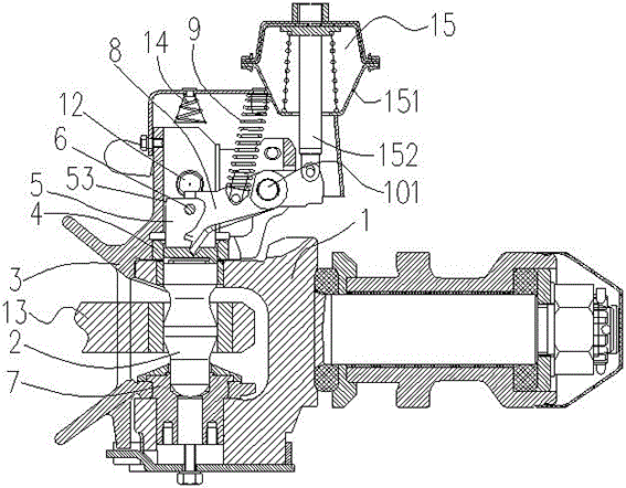
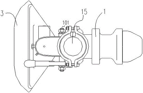
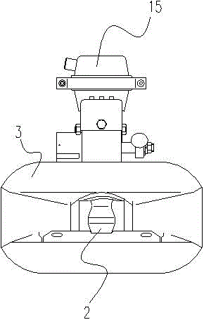
[0033] Example: such as Figure 1 to Figure 3 As shown, a kind of automatic traction device comprises draw bar 1, drag pin 2 and guide shell 3, and guide shell 3 is connected with draw bar 1; Drag pin 2 is placed in the hole of guide shell 3, and drag pin 2 from Go through the guide housing 1, the guide sleeve 4, the trailer ring 13 and the guide sleeve 7 sequentially from top to bottom; Image 6 As shown, the present invention also includes a limit pin assembly 12. The limit pin assembly 12 includes a drag pin locking shaft 121 and a drag pin locking spring 123. The drag pin locking shaft 121 is arranged in the horizontal hole of the guide housing 3 Inside, the drag pin locking spring 123 is located at the rear end of the drag pin locking shaft 121, and the front end of the drag pin locking shaft 121 has a tapered top 1211; figure 1 As shown, the upper corner of the drag pin 2 is provided with a first guide bevel 53 corresponding to the tapered top 1211; Figure 7 As shown,...


PUM


Abstract

An automatic traction device comprises a traction rod, a tow pin and a guiding shell and further comprises a limiting pin assembly which comprises a tow pin locking shaft and a tow pin locking spring. The tow pin locking shaft is arranged inside a transverse hole of the guiding shell, and the tow pin locking spring is arranged at the rear end of the tow pin locking shaft; the front end of the tow pin locking shaft is provided with the tapered top, and a first guiding bevel corner corresponding to the tapered top is arranged at the upper side corner of the tow pin; a second guiding bevel corner corresponding to the tapered top is arranged at the upper side corner of an upper branch of one end of a rocker arm, the rotary axis of the rocker arm is arranged in the middle, and the other end of the rocker arm is provided with a connecting pin; and the automatic traction device further comprises a driving cylinder, a cylinder barrel of the driving cylinder is connected with the guiding shell, and a piston rod of the driving cylinder drives the rocker arm to swing through the connecting pin. Connecting/disconnection of a tractor and a trailer can be completed in a driving cab by an operator.

Description

technical field [0001] The invention relates to the field of tractor connection auxiliary equipment, in particular to an automatic traction device with a limit pin that can be automatically extended / retracted. Background technique [0002] At present, the connecting device of tractors in my country mainly adopts pin-type mechanical connection and hook-and-loop mechanical connection (GB / T4781-847). These two connection methods require two people to work at the same time, one of whom is driving and the other is connecting, and it is not easy to connect when plugging. Medium connection, high labor intensity, low efficiency and poor safety. [0003] Chinese utility model patent CN202345314U discloses a mechanical self-locking automatic connecting device for tractors. The guide housing of the device and the drawbar are connected together through a guide sleeve and a guide sleeve; Over the trailer ring, a U-shaped groove is arranged at the upper end of the bolt, and a cylindrical ...

Claims


Application Information

Patent Timeline
Patent Type & Authority Applications(China)
IPC IPC(8): B60D1/01B60D1/24
CPCB60D1/015B60D1/24
Inventor 赵洪涛宋冠华李海港李学昭
Owner SHANDONG DEFANG HYDRAULIC MACHINERY
Why Eureka
Try Eureka