Methods and apparatus for position sensitive suspension damping

a position sensitive and damping technology, applied in the field of vehicle suspensions, can solve problems such as deformation or breakage of components inside the damping cylinder, and achieve the effect of increasing the damping rate and reducing the chance of damper “bottoming ou

Inactive Publication Date: 2012-12-06
FOX FACTORY
View PDF17 Cites 71 Cited by
  • Summary
  • Abstract
  • Description
  • Claims
  • Application Information

AI Technical Summary

Benefits of technology

[0011]One advantage of some disclosed embodiments is that multiple bypass flow paths enable the vehicle suspension damper to be setup such that the damping rate changes (i.e., is increased) as the damper nears full compression. The increased damping rate, caused by fluid being forced through fewer flow paths formed by the multiple bypass flow paths causes the force opposing further compression of the damper to increase, thereby decreasing the chance that the damper “bottoms out.”

Problems solved by technology

Allowing the damping components to “bottom out” may cause the components to deform or break inside the damping cylinder.

Method used


Image

  • Methods and apparatus for position sensitive suspension damping
  • Methods and apparatus for position sensitive suspension damping
  • Methods and apparatus for position sensitive suspension damping

Examples


Embodiment Construction

[0022]Integrated damper / spring vehicle shock absorbers often include a damper body surrounded by or used in conjunction with a mechanical spring or constructed in conjunction with an air spring or both. The damper often consists of a piston and shaft telescopically mounted in a fluid filled cylinder. The damping fluid (i.e., damping liquid) or damping liquid may be, for example, hydraulic oil. A mechanical spring may be a helically wound spring that surrounds or is mounted in parallel with the damper body. Vehicle suspension systems typically include one or more dampers as well as one or more springs mounted to one or more vehicle axles. As used herein, the terms “down”, “up”, “downward”, “upward”, “lower”, “upper”, and other directional references are relative and are used for reference only.

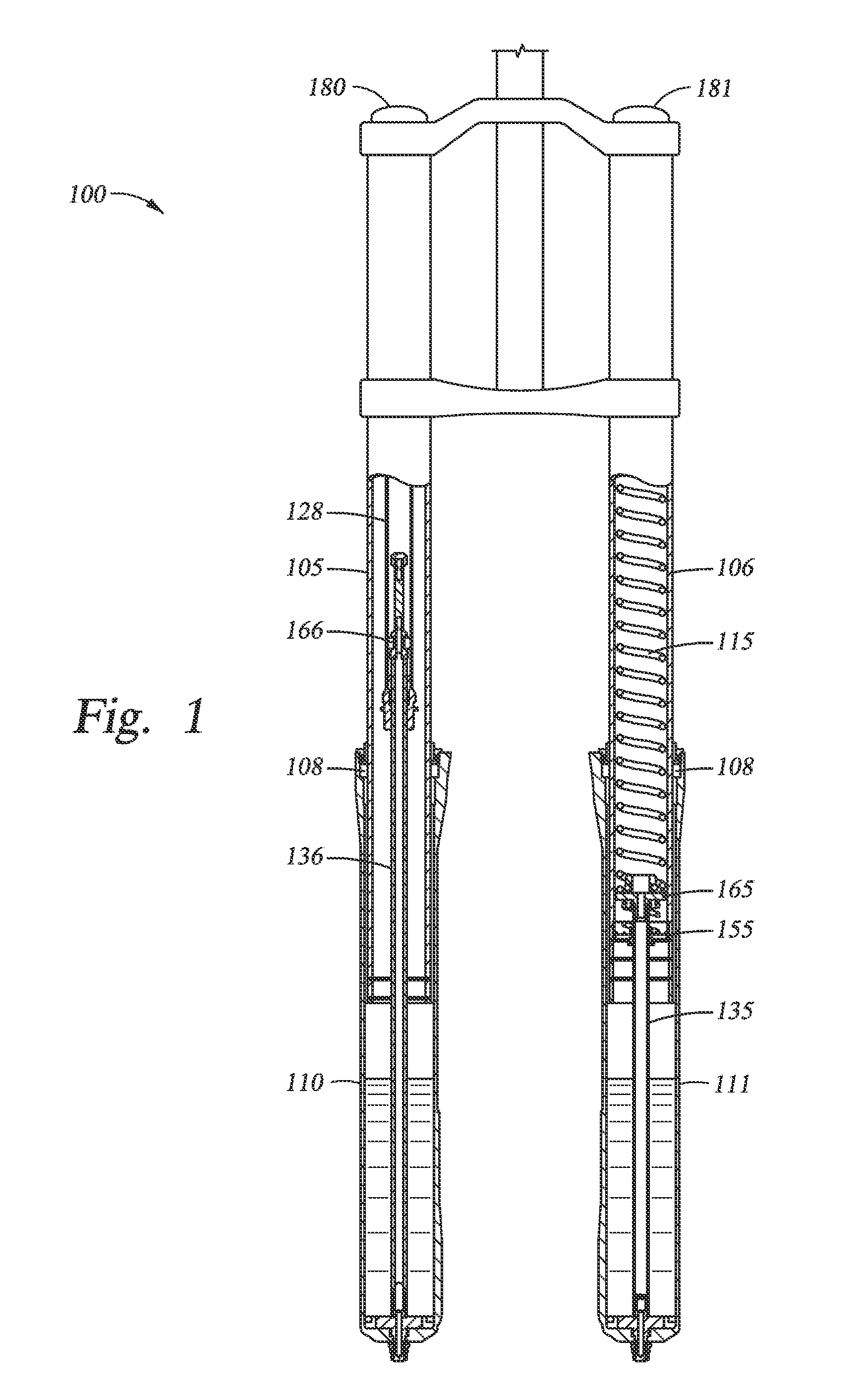
[0023]FIG. 1 shows an asymmetric bicycle fork 100 having a damping leg and a spring leg, according to one example embodiment. The damping leg includes an upper tube 105 mounted in telescopic en...


PUM


Abstract

An apparatus and system are disclosed that provide position sensitive suspension damping. A damping unit includes a piston mounted in a fluid-filled cylinder. A vented path in the piston may be fluidly coupled to a bore formed in one end of the piston rod, creating a flow path for fluid to flow from a first side of the piston to a second side of the piston during a compression stroke. The flow path may be blocked by a needle configured to engage the bore as the damping unit is substantially fully compressed, thereby causing the damping rate of the damping unit to increase. In one embodiment, the piston includes multiple bypass flow paths operable during the compression stroke or the rebound stroke of the damping unit. One or more of the bypass flow paths may be restricted by one or more shims mounted on the piston.

Description

CROSS-REFERENCE TO RELATED APPLICATIONS[0001]This application claims benefit of U.S. Provisional Patent Application Ser. No. 61 / 491,858 (Atty. Dkt. No. FOXF / 0055USL), filed May 31, 2011, and U.S. Provisional Patent Application Ser. No. 61 / 645,465, filed May 10, 2012, which are herein incorporated by reference in their entirety.BACKGROUND OF THE INVENTION[0002]1. Field of the Invention[0003]The invention relates generally to vehicle suspensions and, more specifically, to variable damping rates in vehicle shock absorbers and forks.[0004]2. Description of the Related Art[0005]Vehicle suspension systems typically include a spring component or components and a damping component or components. Often, mechanical springs, like helical springs, are used with some type of viscous fluid-based damping mechanism, the spring and damper being mounted functionally in parallel. In some instances a spring may comprise pressurized gas and features of the damper or spring are user-adjustable, such as b...

Claims


Application Information

Patent Timeline
Patent Type & Authority Applications(United States)
IPC IPC(8): B60G13/08B60G13/10B60G15/06B60G13/06
CPCF16F9/486F16F9/3405F16F9/516F16F9/46B62K25/08B62K2025/048F16F9/342B62K25/06
Inventor ERICKSEN, EVERET O.COX, CHRISTOPHER PAULPELOT, SANTE M.
Owner FOX FACTORY
Why Eureka
Try Eureka