Robot device

A robot and equipment technology, applied in the field of robots, can solve the problems of robot burning, robot power failure, safety hazards, etc., and achieve the effects of simple and convenient operation, increased safety, and safe and stable power supply.

Inactive Publication Date: 2017-12-29
FUZHOU XINGWANGCHENG INFORMATION TECH CO LTD
View PDF7 Cites 5 Cited by
  • Summary
  • Abstract
  • Description
  • Claims
  • Application Information

AI Technical Summary

Problems solved by technology

[0002] At present, the power supply of the robot is to directly insert the connected body connected to it into the power connection chamber of the power supply part to connect to the power supply, and the power supply part will always be connected to the mains. However, the length of the line between the connecting body and the robot is different, and there is no other locking device to lock the connecting body after the connecting body is inserted into the connecting cavity. When the line is kicked, the connecting body will be damaged. Detachment from the electrical connection cavity will lead to a sudden power failure of the robot, and even directly cause the robot to be burned. Therefore, the existing coordination method between the electrical connection body and the electrical connection cavity has potential safety hazards of unstable power supply connection. In addition, when the robot is not in use, the electrical connection body is often pulled out from the electrical connection cavity, which will result in the exposure of the electrical connection cavity, which poses a greater safety hazard

Method used


Image

  • Robot device
  • Robot device
  • Robot device

Examples


Embodiment Construction

[0017] The preferred embodiments of the present invention will be described in detail below in conjunction with the accompanying drawings, so that the advantages and features of the present invention can be more easily understood by those skilled in the art, and the protection scope of the present invention will be defined more clearly.

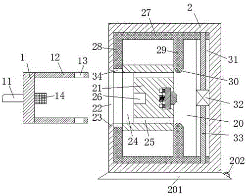
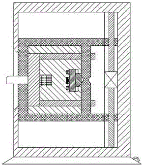
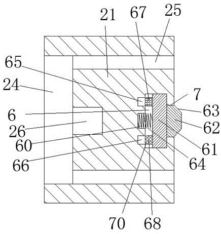
[0018] Refer to Figure 1-4 The robot device shown includes an electrical connection piece connected to the robot via a line 11 and an electrical input piece. The electrical connection piece includes a push-pull block 1. The push-pull block 1 has two opposite ends at the front and rear ends of the right end face. Two inserting rods 12, the right ends of the two inserting rods 12 are both provided with a through cavity 13, the push-pull block 1 is provided with a contact 14 in the middle of the right end surface, the power inlet includes a housing 2, and the housing 2 A suction cup 201 is fixedly installed at the bottom. The upper side of the suc...


PUM


Abstract

The invention discloses a robot device which comprises an electric connecting member and an electric incoming member, wherein the electric connecting member and the electric incoming member are connected with a robot through lines. The electric connecting member comprises a pushing-and-pulling block. The front end and the back end of the right end surface of the pushing-and-pulling block are symmetrically provided with two insertion rods. The right end of each of the two insertion rods is provided with a through chamber. The middle part of the right end surface of the pushing-and-pulling block is provided with a contact. The electric incoming member comprises a housing which is internally provided with a trough. The middle part of the left end surface of the housing is provided with a chamber which is connected with the trough. The whole device can finish switching-off and switching-on of the contact through operation of one motor, namely switching-off and switching-on of the robot. The robot device has advantages of simple and convenient operation, high power supplying stability, safe and reliable operation, and simple and convenient matching operation between the contact and the electric connecting member.

Description

Technical field [0001] The present invention relates to the field of robots, in particular to a robot device. Background technique [0002] At present, when the robot is energized, the connecting body connected to it is directly inserted into the connecting cavity of the power inlet to connect and energize. The power inlet and the mains connection will always be in a energized state. Although this coordination method is more convenient to operate, But the length of the wire between the connected body and the robot is different, and after the connected body is inserted into the connected cavity, there is no other locking device to lock the connected body. When the wire is kicked, the connected body will be caused. Separation from the power connection cavity will cause the robot to suddenly cut off the power, and even directly cause the robot to burn down. Therefore, the existing connection between the power connection body and the connection cavity has a safety risk of instability...

Claims


Application Information

Patent Timeline
Patent Type & Authority Applications(China)
IPC IPC(8): H01R13/627H01R13/629H01R13/703B25J19/00
CPCB25J19/00H01R13/6275H01R13/629H01R13/7035
Inventor 胡龙
Owner FUZHOU XINGWANGCHENG INFORMATION TECH CO LTD
Why Eureka
Try Eureka