Device and method for fixing a push element

A technology for components and clamping components, applied in the field of push-in components, which can solve problems such as low holding force and achieve the effect of allowing precise positioning

Active Publication Date: 2018-01-02
PAUL HETTICH
View PDF7 Cites 1 Cited by
  • Summary
  • Abstract
  • Description
  • Claims
  • Application Information

AI Technical Summary

Problems solved by technology

However, such a latch connection achieves only a relatively low holding force during a standardized stop test of a drawer, where the drawer is pulled out under load.

Method used


Image

  • Device and method for fixing a push element
  • Device and method for fixing a push element
  • Device and method for fixing a push element

Examples


Embodiment Construction

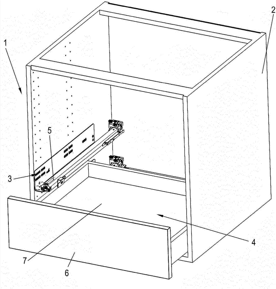
[0023] The furniture 1 comprises: a furniture body 2 , one or more pull-out guides 3 are fixed on the side walls of the furniture body 2 , and the pull-out guides 3 have at least one movable rail 5 . The drawer 4 is displaceably held on two such rails 5, wherein a device 10 is arranged on each rail 5 to fix the drawer 4 to the rails 5, as figure 2 visible in the bottom view. On the bottom 7 of the drawer 4 there are provided first means 10 and second means 10 for fixing the drawer to the respective rail 5 . Each device 10 comprises a housing 15 secured to the front panel 6 and / or bottom 7 of the drawer 4 . At least one device 10 may include lateral, height or depth adjustment structures to position the front panel 6 in a horizontal direction perpendicular to the pull-out direction.

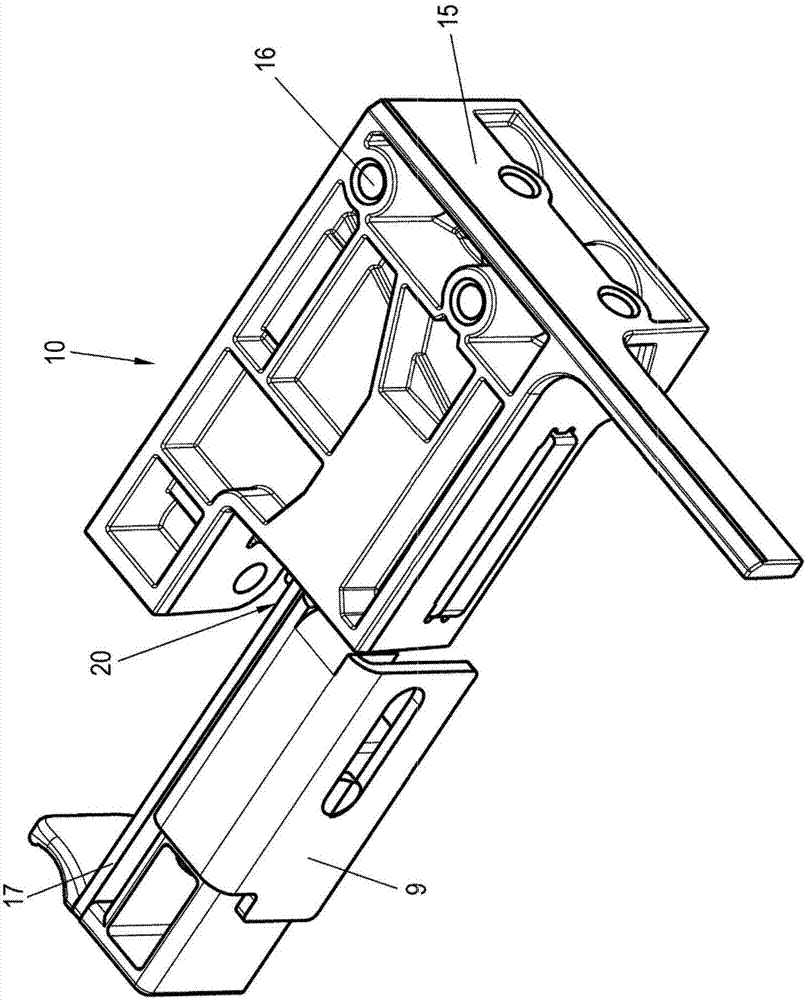
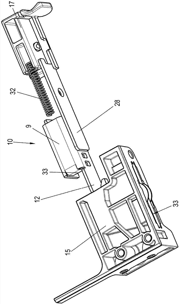
[0024] exist figure 2 , 3 , 4, the device 10 is shown with a housing 15 . The housing 15 is secured to the underside of the drawer 4 by fastening means on the opening 16 , wherein a recepta...


PUM


Abstract

The invention relates to a device for fixing a push element, in particular a drawer box (4) to a rail (5) of a pull-out guide (3), said device comprising a clamping mechanism with a receptacle (20), into which a web-shaped holding part (12) can be inserted, wherein a self-locking clamping element (25) is provided at the receptacle (20), by means of which the holding part (12) is secured in a clamping manner against being pulled out. As a result, a particularly stable fixation of the drawer box (4) to a pull-out guide (3) can be achieved.

Description

technical field [0001] The invention relates to a device for fastening a push-in element, in particular a drawer, to a rail of a pull-out guide, said device comprising a clamping mechanism with a receptacle into which a web-shaped holding part can be inserted. part, wherein a self-locking clamping lever is provided on the receiving part, by means of which the holding part is fastened in a clamping manner against being pulled out. The invention also relates to a method for securing a push-in element. Background technique [0002] EP 1 285 604 discloses a device for fixing a drawer to a rail of a pull-out guide, wherein a base part fastenable to the drawer and a latch element fixable to the pull-out guide are provided. In order to compensate for the distance between the guide rails of the pull-out guide, the latch element can be displaced relative to the base part within a certain tolerance range. Since the latch element and the base part are designed as plastic parts, the h...

Claims


Application Information

Patent Timeline
Patent Type & Authority Applications(China)
IPC IPC(8): A47B88/423A47B88/57
CPCA47B2210/0056A47B88/427A47B2088/4272A47B2088/4276A47B2088/4278A47B88/407A47B2088/4274
Inventor A·斯图福尔J·威德里奇M·布赫梅尔H·迈耶
Owner PAUL HETTICH
Why Eureka
Try Eureka