
Fixing device for steering device

a fixing device and steering device technology, applied in the direction of steering columns, steering components, steering columns, etc., can solve the problems of poor feeling, wear of the cam follower surface, damage to etc., to prevent damage to the cam surface, increase the force for fastening to the fixed bracket, and increase the durability of the tilt telescope steering device

Inactive Publication Date: 2010-05-18
YAMADA MANUFACTURING CO LTD
View PDF6 Cites 41 Cited by
  • Summary
  • Abstract
  • Description
  • Claims
  • Application Information

AI Technical Summary

Benefits of technology

The solution effectively distributes axial force, preventing damage to cam surfaces, improving durability, reducing the operating load, and ensuring stable and accurate tightening movements while maintaining good operability.

Problems solved by technology

This results in wear of the cam follower surface 51 caused by contact friction at the cam follower surface 51 and the frequent use of the lever.
Therefore the durability of the tilt telescope steering device is damaged.
Also, as a result of the wear of the cam follower surface 51, the surface becomes rough, which causes the problem of poor feeling when operating (the load when operating the lever becomes heavier).
However, there is a limit taking the size of the cam into consideration, and with the present size of cams increasing the number of cam surfaces is difficult.

Method used


Image

  • Fixing device for steering device
  • Fixing device for steering device
  • Fixing device for steering device

Examples


Embodiment Construction

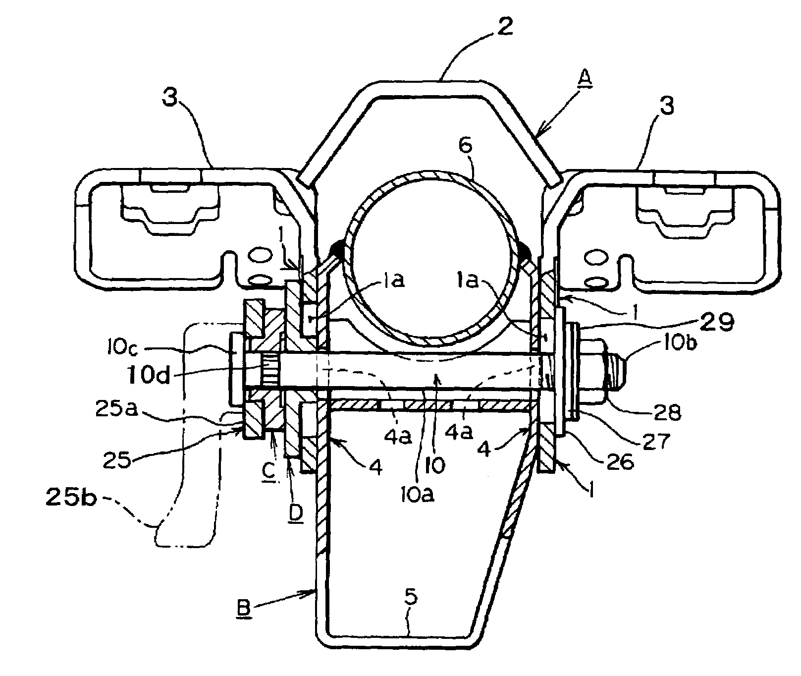
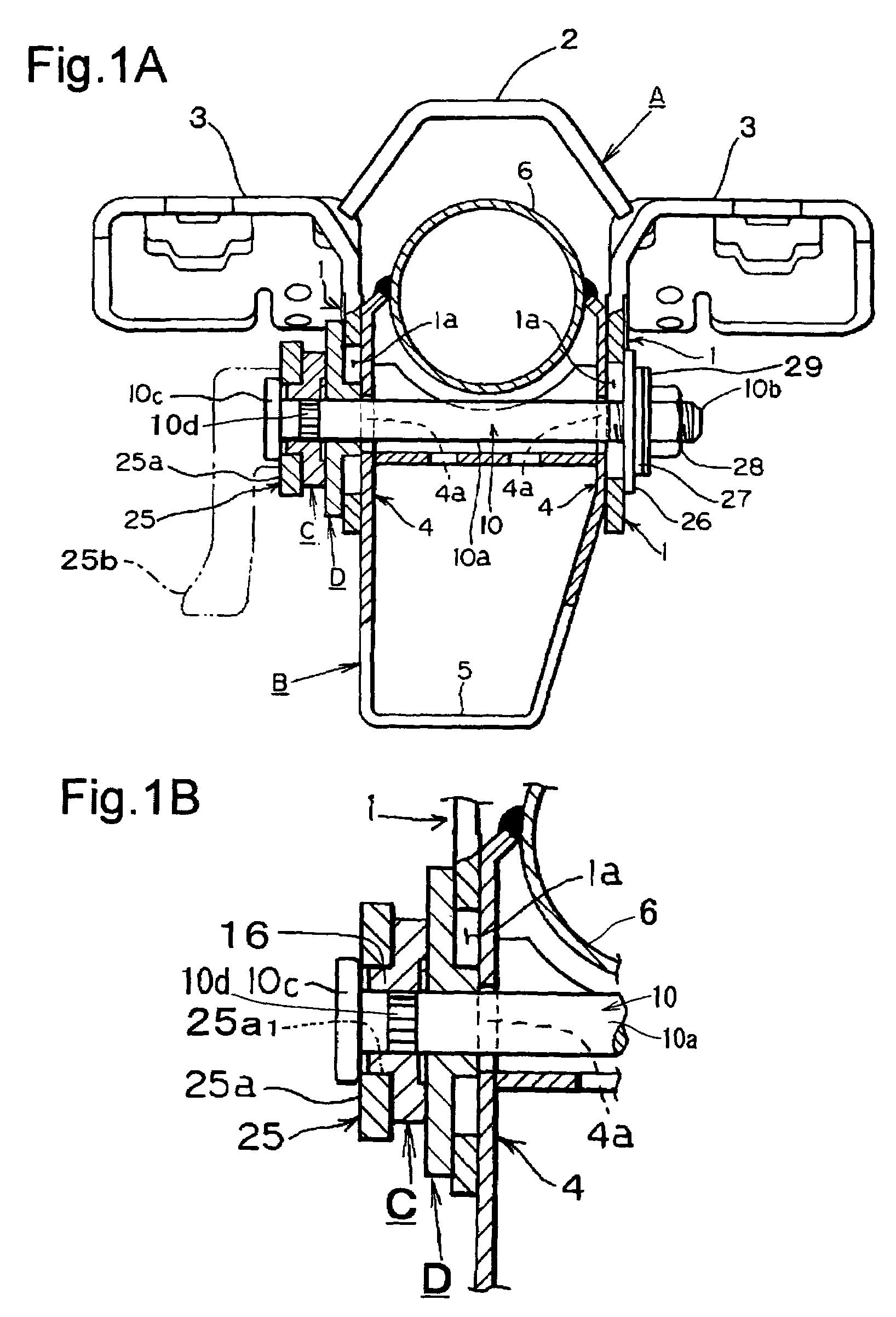
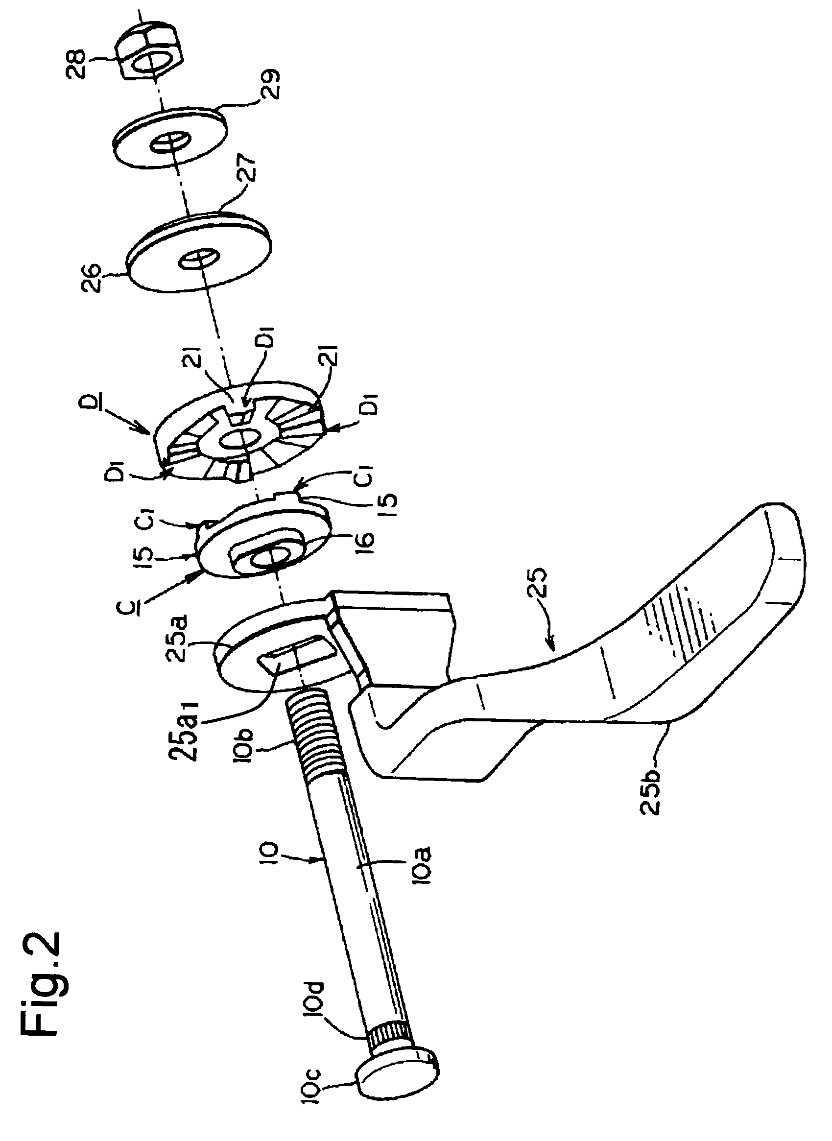
[0026]The following is an explanation of the preferred embodiments based upon the drawings. As shown in FIGS. 1 and 11 and others, the present invention includes mainly a fixed bracket A, a movable bracket B, a lock bolt 10, an operation lever 25, a main drive cam C, and a driven cam D. As shown in FIG. 11, the fixed bracket A is formed mainly from fixed side parts 1, 1, a connection part 2, and installation parts 3, 3. The two fixed side parts 1, 1 are substantially flat plate parts parallel and in confrontation. Tilt adjustment elongated holes 1a, 1a are formed in the two fixed side parts 1, 1 in an approximately vertical direction, through which a lock bolt 10 that is described later passes.

[0027]The two fixed side parts 1, 1 are connected at the top to a connecting part 2 by welding means or similar. The connecting part 2 is formed into an approximately trapezoidal gate shape, or arch shape when viewed from the front. Also, the horizontally shaped installation parts 3, 3 are for...


PUM


Abstract

To provide a fixing device for a steering device capable of tilt adjustment and having a very simple cam structure.The fixing device includes a fixed bracket; a movable bracket; a lock bolt that passes through the fixed bracket and the movable bracket; a main drive cam, through which the lock bolt passes, and that is fitted to rotate freely; and a driven cam, through which the lock bolt passes, and that is fitted unrotatably. Cam operation parts are formed on the main drive cam and the driven cam respectively. Cam operation parts on both sides are always in contact with the other side while the main drive cam and the driven cam separate and come close in the axial direction, and the diameter of the driven cam is larger than the diameter of the main drive cam.

Description

BACKGROUND OF THE INVENTION[0001]1. Field of the Invention[0002]The present invention relates to a fixing device for a steering device capable of tilt adjustment and having a very simple cam structure.[0003]2. Description of the Related Art[0004]Among tilt telescopic steering devices in which the height of a steering wheel and the orientation of the axis can be changed as appropriate to the body build and driving attitude of the driver, steering devices provided with a tilt adjustment mechanism whose structure includes an operation lever fitted to a lock bolt that passes through side plates of a fixed bracket installed on the car body and side plates of a movable bracket in which the steering column is installed, and by rotating the operation lever the side plates of the fixed bracket and movable bracket press against each other to lock the tilt are known.[0005]Among this type of device are devices that include two cam members: one cam member fitted to the fixed bracket side, and th...

Claims


Application Information

Patent Timeline
Patent Type & Authority Patents(United States)
IPC IPC(8): B62D1/18B62D1/00
CPCB62D1/184
Inventor HIROOKA, KOUJI
Owner YAMADA MANUFACTURING CO LTD
Learn More