Fold-up storage container

a storage container and fold-up technology, applied in the field of containers, can solve the problems of relatively high cost of shipping such containers from a manufacturing plant to a use site such as a warehouse or wharf, and achieve the effect of convenient folding and fastening

Inactive Publication Date: 2003-08-14
LAU DAVID M K
View PDF10 Cites 39 Cited by
  • Summary
  • Abstract
  • Description
  • Claims
  • Application Information

AI Technical Summary

Benefits of technology

[0007] An object of the present invention is to provide a storage container including sub-assembly components which all may be transported in a relatively thin package, and readily folded-up and fastened together at a use site to assemble a useable storage container.
[0011] Another object of the invention is to provide a fold-up shipping container having at the corners of a roof panel thereof L-shaped stacking blocks which both enable a plurality of containers to be stacked vertically, while protecting a lifting ring protruding upwards from an end post at each corner from damage when the containers are stacked.
[0017] Briefly stated, the present invention comprehends a storage container for freight and other such goods, the container being transportable to a storage site in a substantially flat or knocked-down configuration, and readily assembled into a fully operational and useable storage container by means of simple assembly steps performable by relatively low skill-level workmen, the steps including folding up subassembly components from a parallel, flattened configuration to a perpendicular, upright position.
[0020] According to another aspect of the invention, each roof panel tubular hinge fastener lug protrudes downwardly from a horizontally disposed ring which is concentric with the roof panel, the ring being formed of four straight, square cross-section tubular ribs arranged into a rectangle. The outer vertical surfaces of opposed parallel pairs of roof ring ribs are spaced slightly closer together than the inner vertical surfaces of pairs of upper peripheral ribs which protrude upwards from pairs of side and end panels. This arrangement allows the roof ring to be insertably received within a ring formed by end and side panel upper peripheral ribs. The roof panel preferably has a downwardly located peripheral flange spaced outwardly from the roof ring ribs, at a distance slightly greater than the spacing between outer corresponding surfaces of the end panel and side panel upper peripheral ribs, thus overlapping the end and side panels to form a weather-tight seal. In a variation of this aspect of the invention, both the roof and side and end panel ribs have right triangular cross-sectional shapes, the hypotenuses of the ribs angling downwardly towards the center of the container and conformally contacting one another in a dual ramp arrangement to facilitate sliding the roof panel into place atop the side and end panels.
[0022] According to another aspect of the invention, a pair of rectangular block-shaped connector castings is installed at each of the four corners of the base, each connector casting having a pair of mutually perpendicular bolt bores. A first, corner connector casting is located directly at a base corner, and a second, offset connector casting is rotated 90 degrees and spaced longitudinally a short distance along an edge of the base, inwards from the corner. This arrangement enables pairs of connector castings of adjacent containers to be fitted together in both side-by-side and end-to-end configurations, and bolted together to secure the containers in a selected configuration.
[0023] According to another aspect of the invention, a tubular L-shaped stacking block protrudes upwardly from each of the four corners of the roof panel, the stacking blocks enabling a plurality of containers to be stacked vertically, while protecting a lifting ring installed at each corner from damage when the containers are vertically stacked.

Problems solved by technology

There fore, shipping such containers from a manufacturing plant to a use site such as a warehouse or wharf is relatively expensive.

Method used


Image

  • Fold-up storage container
  • Fold-up storage container
  • Fold-up storage container

Examples


Embodiment Construction

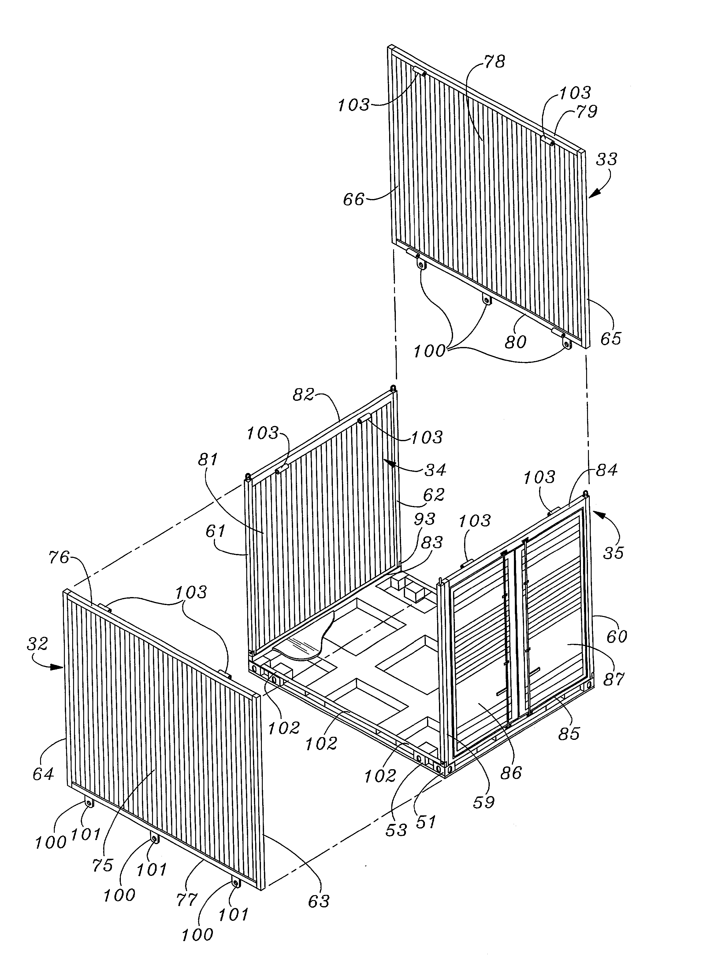
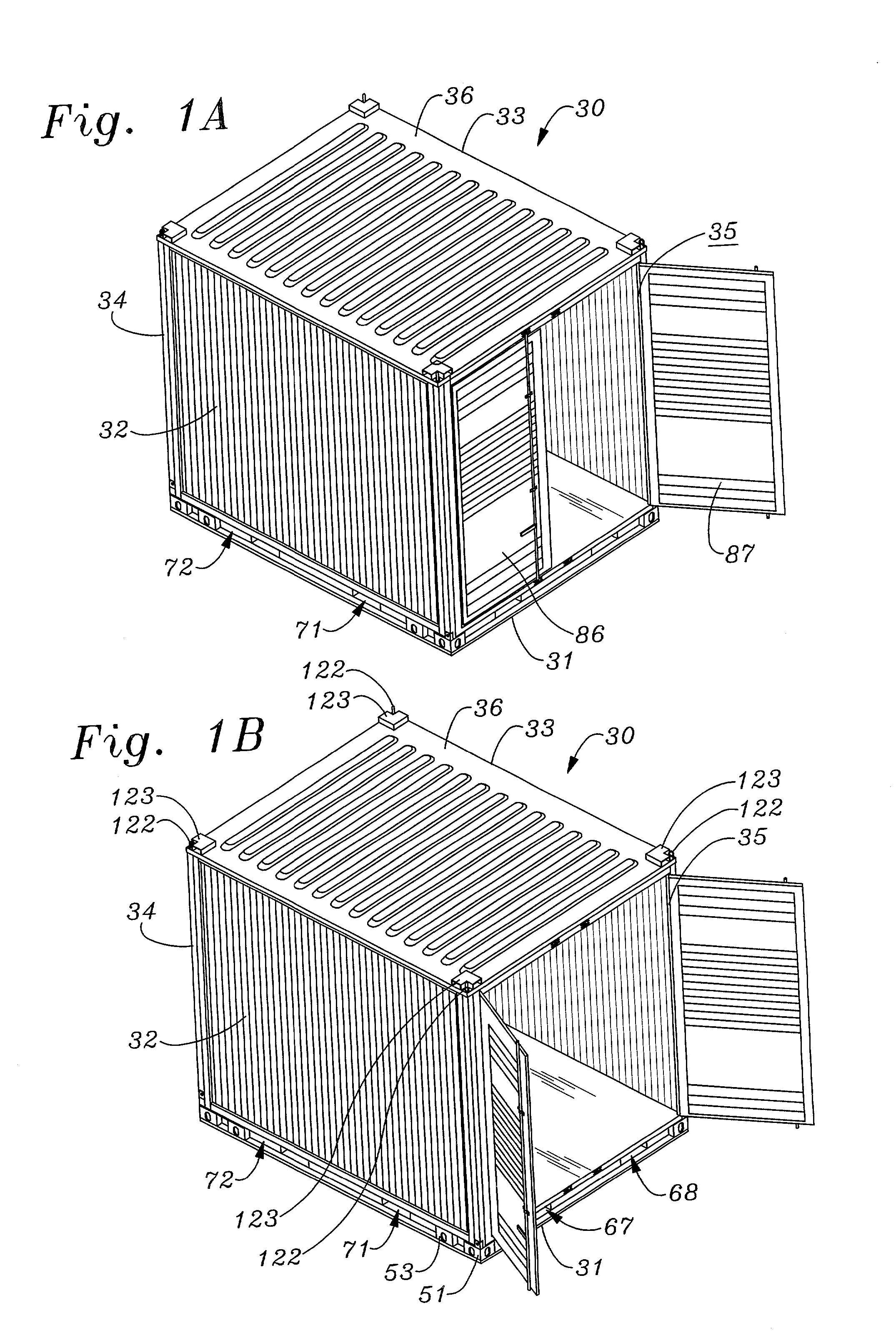
[0045] In the ensuing description, FIGS. 1-17 illustrate a fold-up storage container according to the present invention, while FIGS. 18 and 19 illustrate how a plurality of fold-up storage containers according to the present invention may be coupled together. FIG. 20 illustrates an alternate embodiment of a fold-up storage container according to the present invention.

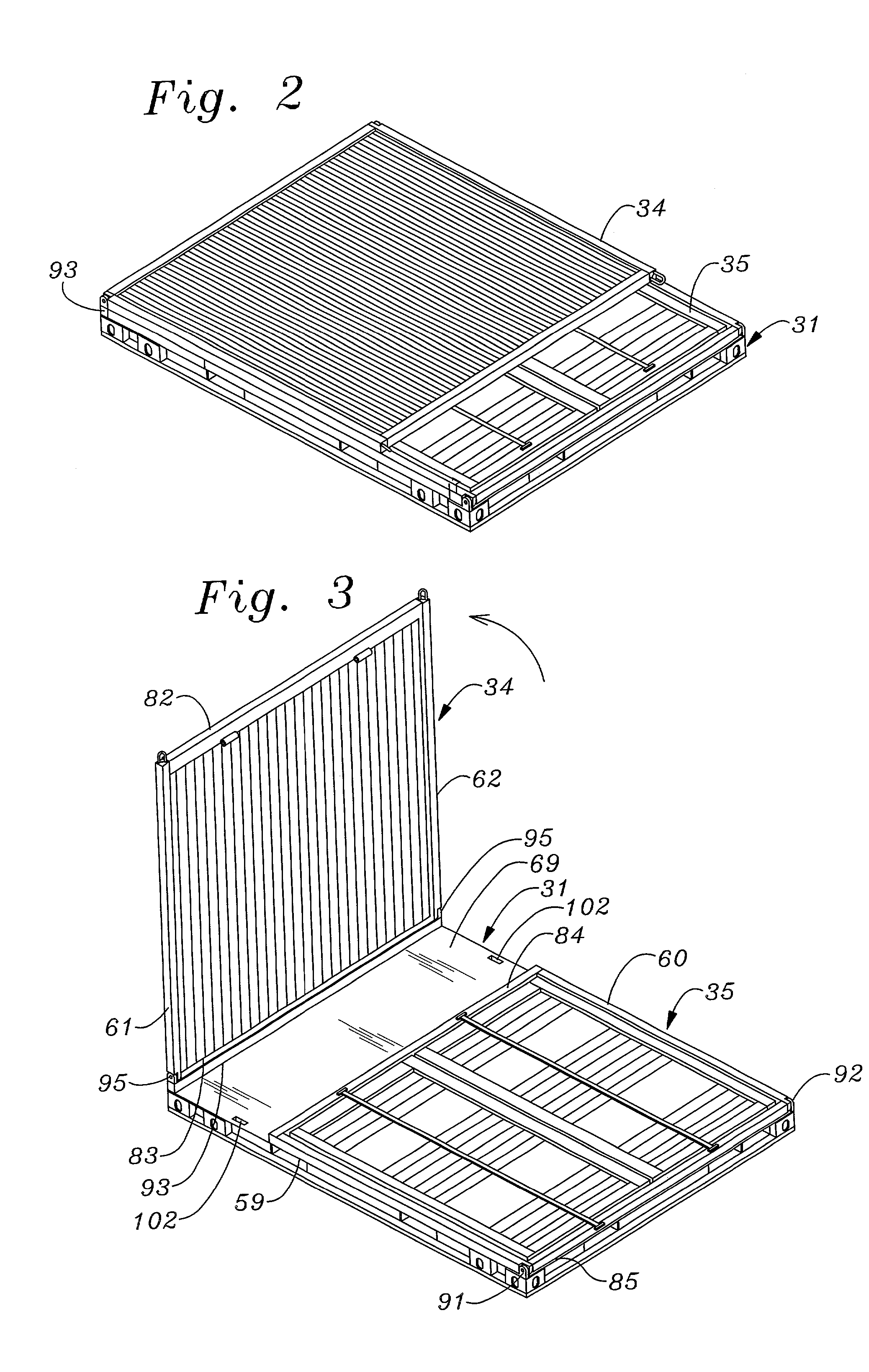
[0046] More specifically, FIG. 1 illustrates a fully assembled fold-up storage container 30 according to the present invention, FIGS. 2-7 show component parts of container 30, including subassemblies which are folded up from a compact arrangement suited for transporting and storing an unassembled container, and FIGS. 9-17 illustrate structural details of storage container 30.

[0047] Referring first to FIGS. 1 and 7, a fold-up storage container 30 according to the present invention may be seen to include a plurality of generally flat, rectangularly-shaped panels which are fastened together to form a generally rectangularl...


PUM


Abstract

A freight storage container includes six rectangularly-shaped panels including a base panel, a front end panel hingedly fastened to a front edge of the base panel and pivotable into overlying contact therewith, and a rear panel hingedly fastened to a rear edge of the base panel and pivotable downwards to overlie the front end panel. The container is assembled on-site by folding upwardly the rear and front panels, installing two side panels in the base, and fastening a roof panel to upper peripheral edge walls of the side and end panels, by novel fastener joints each consisting of a tubular hinge lug member protruding downwards from a lower inside surface of the roof panel, a coaxially aligned tubular side panel hinge lug member protruding inwardly from a side panel, and a stainless steel friction pin forced into an interference fit within coaxially aligned bores of the two lugs.

Description

[0001] 1. Field of the Invention[0002] The present invention relates to containers of the type used to store goods such as articles of freight being temporarily held at a shipping source or destination. More particularly, the invention relates to a fold-up storage container which may be transported to a storage site in a relatively flat, compact package, and folded upwards therefrom to construct a walk-in container which is closable and lockable to secure goods placed within the container from pilferage and damage by the elements.[0003] 2. Description of Background Art[0004] Containers used to store goods at warehouses, wharves and similar locations typically consist of rectangularly-shaped box-like structures which are constructed from rectangularly-shaped metal panels that are fastened together to form the container. The panels are customarily made of corrugated steel plates which are bolted or welded together to form the container. Most such containers have a front end panel prov...

Claims


Application Information

Patent Timeline
Patent Type & Authority Applications(United States)
IPC IPC(8): B65D88/00B65D88/12B65D88/52
CPCB65D88/005B65D88/526B65D88/522B65D88/12
Inventor LAU, DAVID M.K.
Owner LAU DAVID M K
Why Eureka
Try Eureka