Leaf seal, in particular for a gas turbine

a gas turbine and leaf seal technology, applied in the direction of engine seals, leakage prevention, machines/engines, etc., can solve the problems of limiting the service life of the seal, and affecting so as to improve the sealing effect of leaves

Inactive Publication Date: 2008-01-10
ANSALDO ENERGIA IP UK LTD
View PDF27 Cites 36 Cited by
  • Summary
  • Abstract
  • Description
  • Claims
  • Application Information

AI Technical Summary

Benefits of technology

[0030] Finally, the fastening of the leaves in the leaf seal can be improved by the leaves each being subdivided into a head part having the spacer and a sealing part and by the sealing part being inclined relative to the head part.

Problems solved by technology

However, they offer the advantage of low rotational friction and of a therefore virtually unlimited service life.
On the other hand, brush seals have higher friction losses on account of the friction between the bristle ends and the rotor shaft.
This results in wear, which limits the service life of the seal.
Firstly, the axial pressure difference that they can withstand is still fairly low.
In the case of the brush seals, this is due to the bristles, which have the same stiffness in the axial and circumferential directions: high pressures can cause the bristles to blow back on themselves in the axial direction.
The capability of the seals to allow a significant radial movement and to resist it is also low.

Method used


Image

  • Leaf seal, in particular for a gas turbine
  • Leaf seal, in particular for a gas turbine
  • Leaf seal, in particular for a gas turbine

Examples


Embodiment Construction

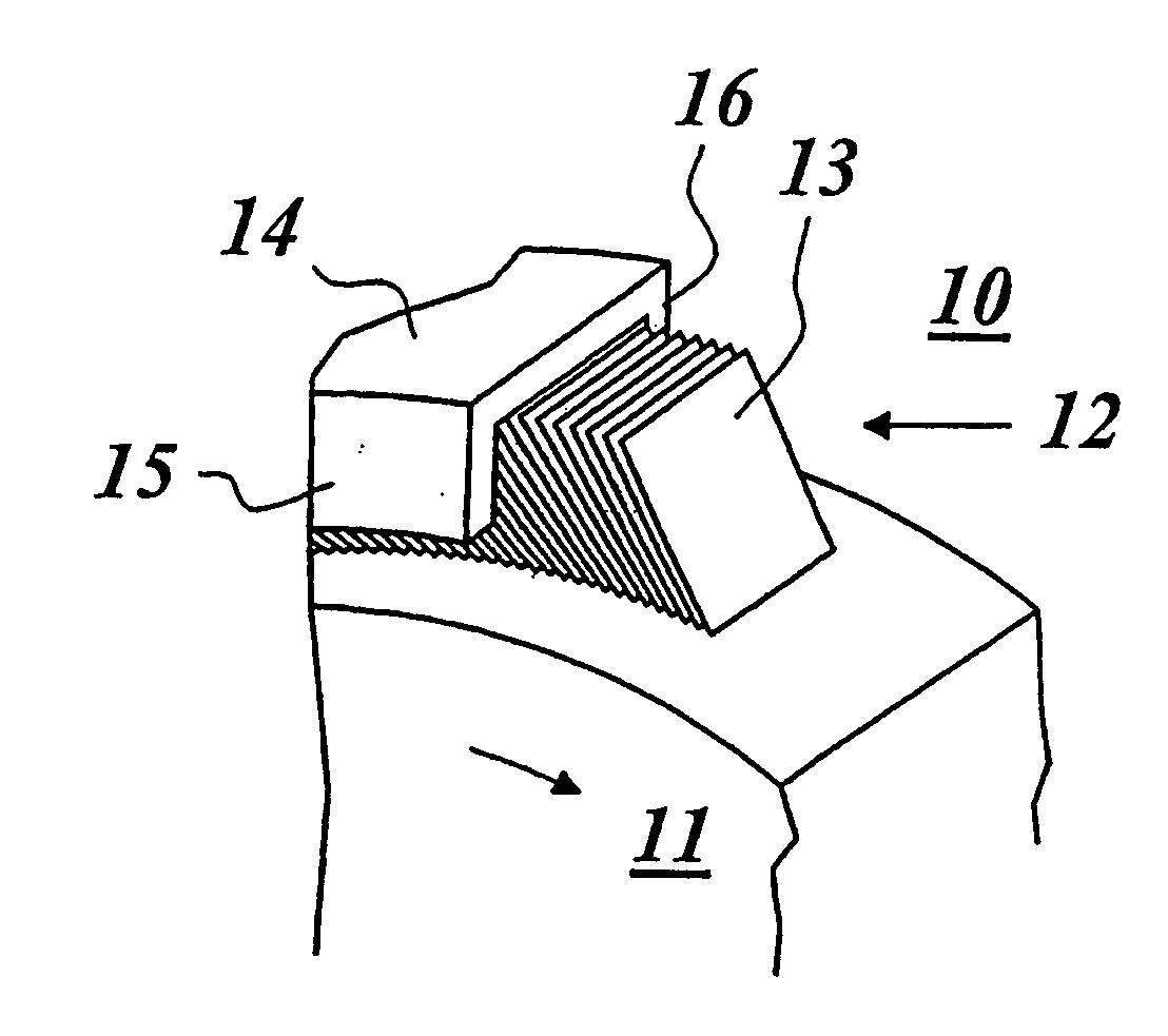
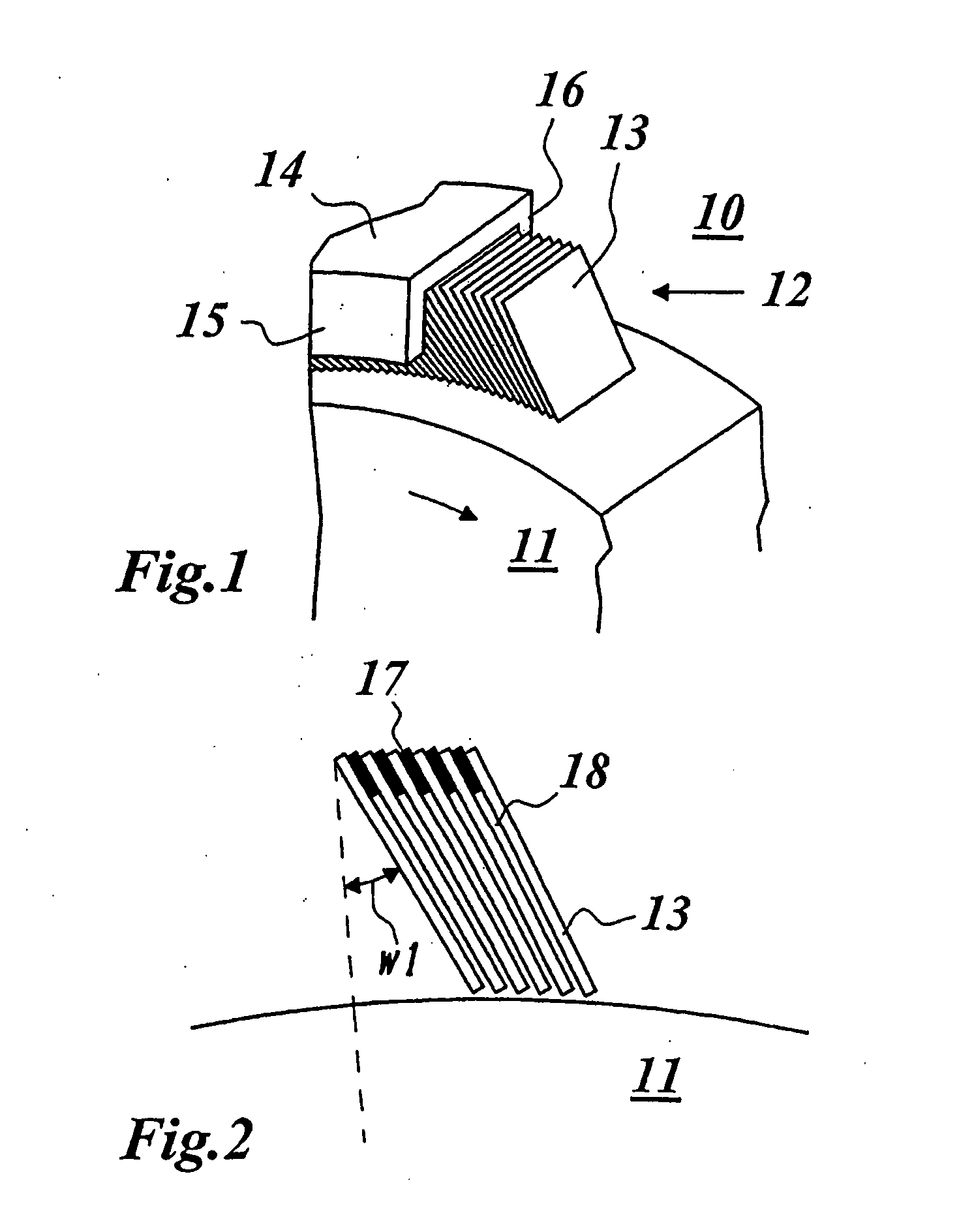
[0043] Shown in FIG. 1 in a perspective side view is the typical construction of a leaf seal as used in a gas turbine. The leaf seal 12 seals a rotor shaft 11, rotating in the arrow direction, of the gas turbine 10 with respect to a housing 14. A stack of tightly spaced-apart thin leaves 13 is arranged in a ring in the annular intermediate space between the rotor shaft 11 and the housing 14. With their surface, the leaves 13 are oriented parallel to the axis of rotation of the machine. According to FIG. 2, the leaves are tilted from the radial direction by an angle w1 and have a narrow gap or intermediate space 18 between them, which is preferably established by spacers 17 arranged between the leaves 13. The spacers 17 of FIG. 2 are shown as separate elements. However, they may also be integrated in the leaves as shown in FIGS. 4-6 and 11.

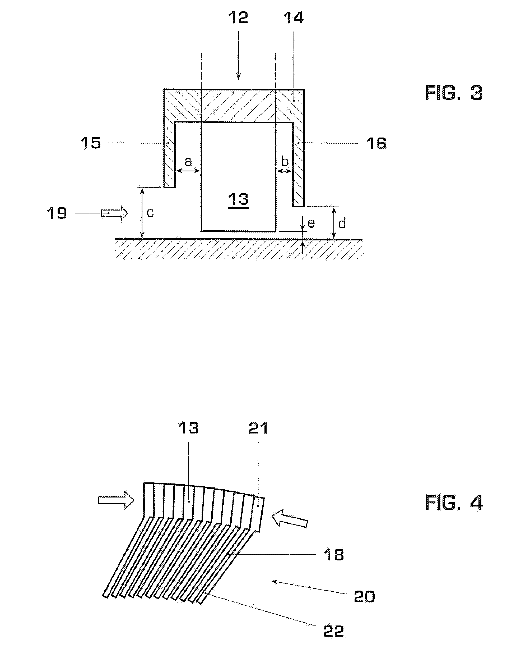
[0044] According to FIGS. 1 and 3, the air flow through the leaves 13 can be varied by using a front and a rear end plate 15 and 16, respectively...


PUM


Abstract

A leaf seal for sealing a shaft rotating about an axis, in particular in a gas turbine, includes a plurality of spaced-apart leaves disposed in a concentric circle around the axis and fixed in position. Each of the leaves includes a surface oriented essentially parallel to the axis and an integrally formed element configured to position and retain the leaves in the leaf seal.

Description

[0001] This application is a continuation of International Patent Application No. PCT / EP2005 / 056164, filed on Nov. 23, 2005, which claims priority to German Patent Application No. DE 10 2004 059 858.4, filed on Dec. 11, 2004. The entire disclosure of both applications is incorporated by reference herein.TECHNICAL FIELD [0002] The present invention relates to sealing in rotating machines and in particular relates to a leaf seal for sealing a shaft rotating about an axis. BACKGROUND [0003] A gas turbine includes a rotor, on which various stages with compressor blades and turbine blades are provided, and of a stator housing. The rotor is mounted in bearings at each end of the rotor shaft. [0004] The control of the gas flow inside the gas turbine is of paramount importance with regard to both the functionality and the effectiveness. Sealing techniques are used at various locations along the rotor shaft in order to reduce the axial gas flow along the shaft. This is especially important n...

Claims


Application Information

Patent Timeline
Patent Type & Authority Applications(United States)
IPC IPC(8): F16J15/44
CPCF16J15/3292F01D11/001
Inventor HOEBEL, MATTHIASRHODES, NIGEL ANTHONYSUMMERSIDE, IAN JAMES
Owner ANSALDO ENERGIA IP UK LTD
Why Eureka
Try Eureka