Light bar and method for making

a technology of light bars and assembly methods, applied in the direction of instruments, anti-theft devices, lighting support devices, etc., can solve the problems of high risk of manufacturing process errors, dense wiring scheme in interiors, and high interior complexity, and achieve reliable and repeatable registration, the effect of reducing the amount of loose wiring

Active Publication Date: 2009-01-13
FEDERAL SIGNAL CORPORATION
View PDF85 Cites 40 Cited by
  • Summary
  • Abstract
  • Description
  • Claims
  • Application Information

AI Technical Summary

Benefits of technology

[0007]The light bar of the invention is of a substantially modular construction based on mounting two or more light beam assemblies on a single circuit board. Each board is fabricated with keys that either guide or dictate a precise mounting of the light beam assemblies onto the board. In addition, the circuit boards are keyed to mounting surfaces in the housing of the light bar so that the circuit boards are precisely mounted with respect within the cavity of light bar housing. This dual registration of the light beam assemblies on the circuit boards and the boards in the cavity of the light bar results in a reliable and repeatable registration of the light beam assemblies with the lenses of the light bar housing. Moreover, by providing circuit boards that mount more than one light beam assembly, the invention substantially reduces the amount of loose wiring in the cavity of the light bar housing.
[0012]Preferably, the circuit board is a thermally conductive circuit board sourced from any of several vendors that communicates control signals to the light beam assemblies, sinks and radiates heat generated by the assemblies and provides mechanical and electrical stability over the environmental conditions to which the light bar is exposed. In the illustrated embodiment of the invention, each of the circuit boards is connected to a controller by a single cable. The controller delivers power and control signals to each of the circuit boards via the single cable connection. In turn, the controller receives power and control signals from a power source and a control head, respectively. The power source may be a battery such as the vehicle's battery or it may be a fuel cell, battery, ultra capacitor (e.g., Maxwell Technologies, San Diego, Calif.) or an array of solar cells. In one embodiment of the invention, the power source is located at the light bar so that power line cables running from the vehicle to the light bar are not required. In this regard, the light bar is made entirely wireless by adding a receiver to the light bar that receives low energy radio frequency (RF) signals from a transmitter associated with the control head.
[0016]In keeping with another aspect of the invention, the modular construction of the light bar makes its assembly easy, quick and error resistant. First, the circuit boards are fabricated in accordance with the types of light beam assemblies to be added. For example, if the light beam assemblies are solid state devices, the fabrication process preferably includes adding the LEDs or other solid state device to the circuit board as part of the fabrication process. With the fabricated boards as a starting point, they are each then populated with two or more light sources in accordance with a customer's requirements (e.g., color, flashing, rotating ). Because each of the boards includes keys to register the light beam assemblies into a proper position, they are reliably fastened to the circuit boards at the right locations. Then each of the circuit boards is fastened into the housing of the light bar. As the boards are placed into the housing, they are registered to the housing with respect to one or more references, which aligns each of the light sources on the circuit board with a lens in the housing.

Problems solved by technology

Often the interior spaces of light bars house an assortment of individual light assemblies and wires to each assembly with associated connectors, making the interiors densely packed with complex wiring schemes.
These designs have evolved into highly complex interiors that are time consuming to assemble and tend to discourage automation of the assembly.
Because the manufacturing process remains dependent on manual assembly, there is a higher than desirable risk of errors in the manufacturing process.
In addition to presenting manufacturing challenges, the multiple connections in the wiring schemes of the interior spaces of light bars create points of potential mechanical and electrical failure.
Multiple individual wire connectors may fail because of vibration, the stress of temperature cycling, accidental tensioning of the wire during assembly or repair and other common sources of wear and tear.
Servicing these many mechanical connections disrupts service and gives rise to reliability issues.
Also, service requirements add expense to the light bar.

Method used


Image

  • Light bar and method for making
  • Light bar and method for making
  • Light bar and method for making

Examples


Embodiment Construction

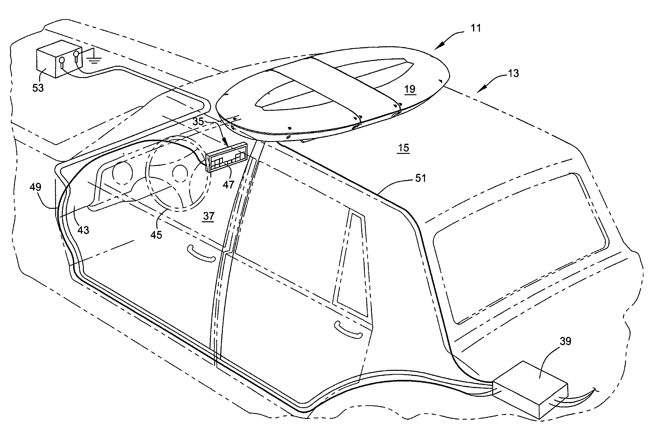
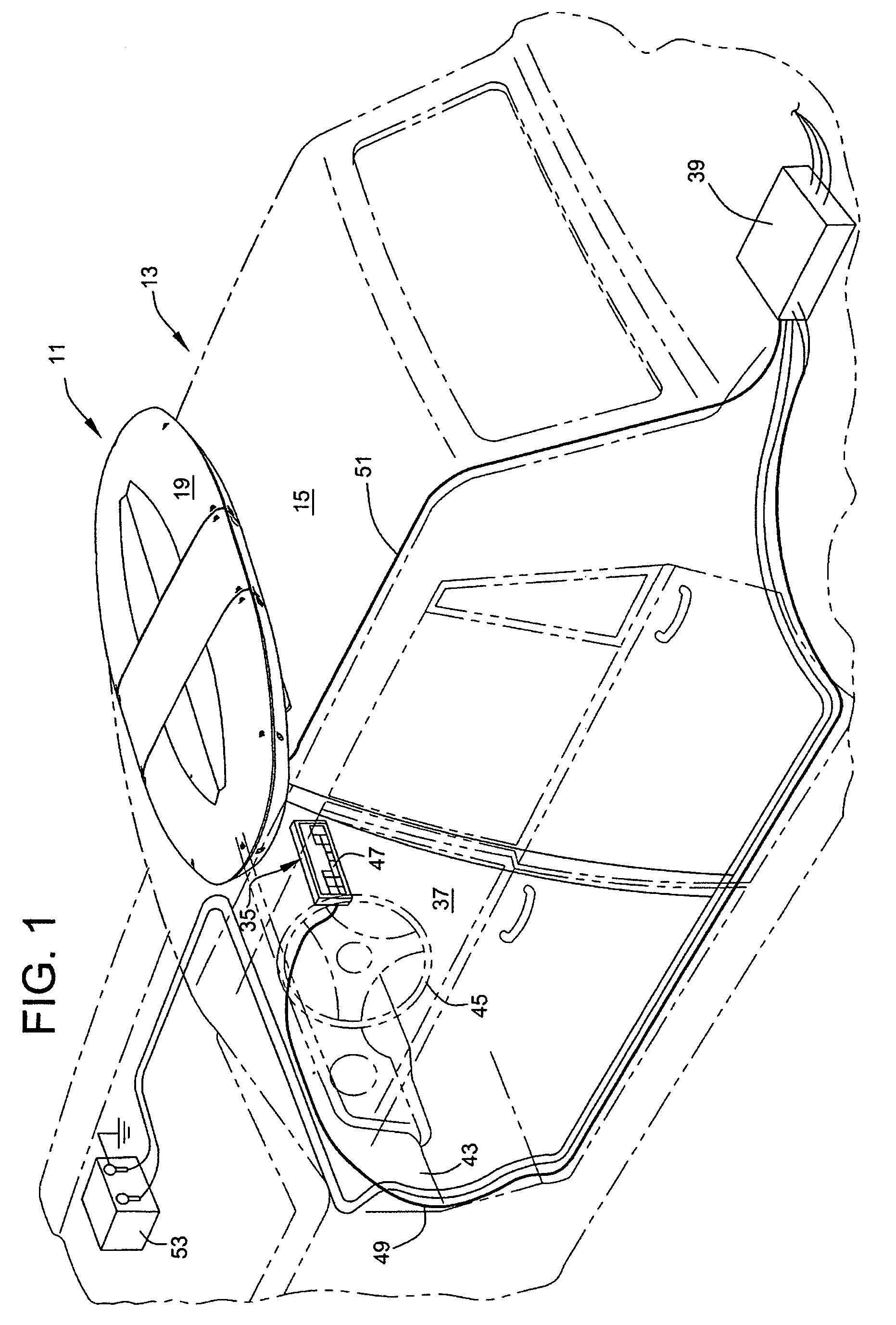
[0035]Turning to the drawings and referring first to FIG. 1, an emergency signaling system 11 according to a preferred embodiment of the invention is installed in an exemplary emergency vehicle 13 shown in broken lines. The system 11 includes a plurality of light beam assemblies or signaling devices best shown in FIGS. 6 and 7. The emergency signaling system 11 is mounted to a roof 15 of the vehicle 13.

[0036]Emergency signaling systems of the type mounted to the roofs of emergency vehicles are commonly called “light bars” because they are typically shaped as a bar traversing the vehicle's roof. In keeping with this convention, the illustrated emergency signaling system 11 is hereinafter referred to as a “light bar” since it is primarily intended for mounting to the roofs of emergency vehicles such as the roof 15 of the illustrated vehicle 13. However, those skilled in the art will appreciate that the manufacturing technique described hereinafter for the illustrated light bar is appl...


PUM

PropertyMeasurementUnit
thermally conductiveaaaaaaaaaa
poweraaaaaaaaaa
coloraaaaaaaaaa

Abstract

A light bar is described that is of a modular construction based on one or more large circuit boards that are populated with light beam assemblies and then fastened to an interior space of the light bar housing. Keys that automatically align the light beam assemblies on each of the boards precisely control placement of the assemblies on the board. In turn, each of the boards is keyed to the interior of the light bar housing so that when the board is fastened to the housing the light beam assemblies are automatically registered into alignment with the lenses in the housing so that the beams from the assemblies are properly oriented. The light bar is inexpensive to fabricate and can be assembled quickly and reliably, yet it provides for a high degree of customization, which is a requirement in the emergency vehicle lighting industry.

Description

TECHNICAL FIELD[0001]The invention is generally directed to signaling systems for emergency vehicles and, more particularly, to warning light assemblies for mounting to emergency vehicles.BACKGROUND OF THE INVENTION[0002]A common type of emergency warning system for a vehicle is commonly called a “light bar.” Typically light bars are mounted to roofs of vehicles and wired to power sources in the engine compartments and controlled from control heads mounted in the passenger compartments.[0003]Customer demands have driven light bars toward highly customizable designs. Manufacturers of light bars often start with a standard housing and then offer an array of alternative types of lighting devices to populate the interior of the light bar. For example, customers may ask for different mixes of takedown lights and alley lights, whose functions are suggested by their names. Customers may also ask for lights of different colors and different types of light sources such as light emitting diod...

Claims


Application Information

Patent Timeline
Patent Type & Authority Patents(United States)
IPC IPC(8): B60Q1/00
CPCB60Q1/2611F21S48/10B60Q1/52F21V23/04Y10T29/49826Y10T29/49002F21S41/148F21S41/151F21S41/285F21S41/321F21S41/323F21S43/13F21S43/14F21S43/15F21S43/195F21S43/31F21S43/37F21S45/10F21S45/47F21S41/00
Inventor GERGETS, PAUL M.FLESZEWSKI, VINCE S.MOSTELLO, ALLAN J.
Owner FEDERAL SIGNAL CORPORATION
Why Eureka
Try Eureka