
filter element with removal element

A filter element and buffer element technology, which is applied in the direction of filtration separation, membrane filter, fixed filter element filter, etc., can solve problems such as disconnection and filter body damage, achieve low cost and overcome adhesion friction

Active Publication Date: 2020-05-12
ROBERT BOSCH GMBH
View PDF3 Cites 0 Cited by
  • Summary
  • Abstract
  • Description
  • Claims
  • Application Information

AI Technical Summary

Problems solved by technology

[0003] If the filter is to be removed from the housing, there is a risk that the filter body is damaged and broken, so that only a part of the filter can be removed

Method used


Image

  • filter element with removal element
  • filter element with removal element
  • filter element with removal element

Examples


Embodiment Construction

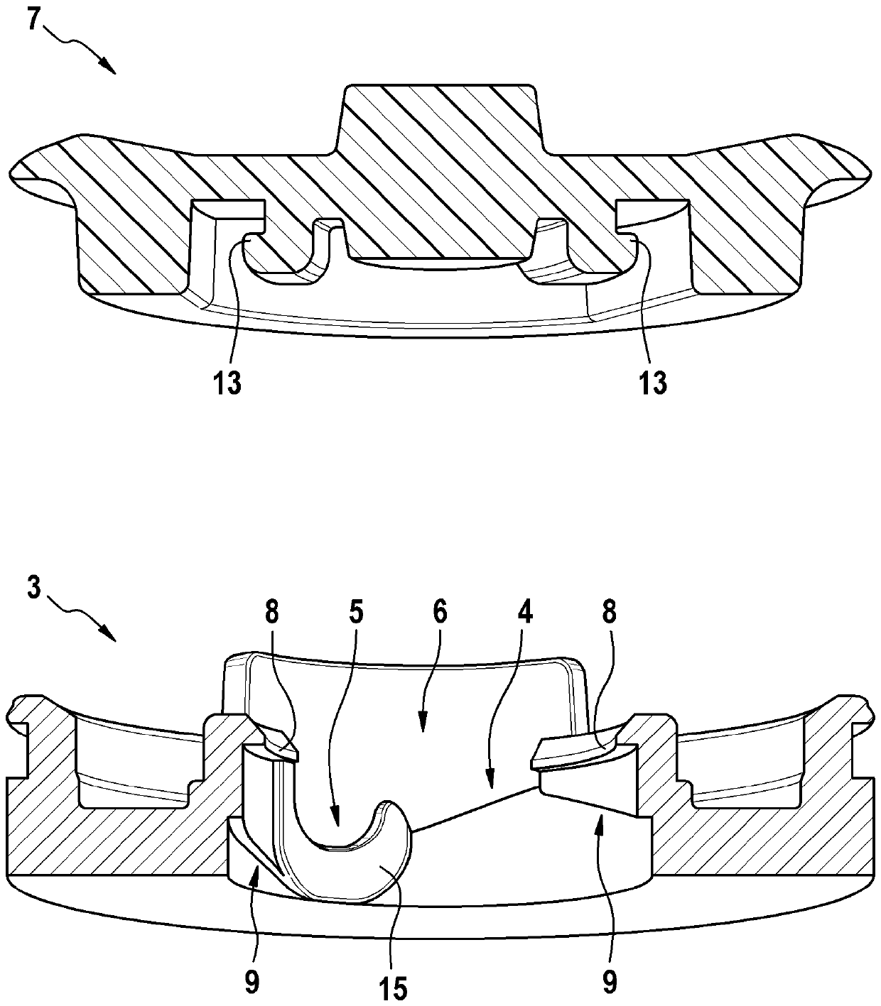
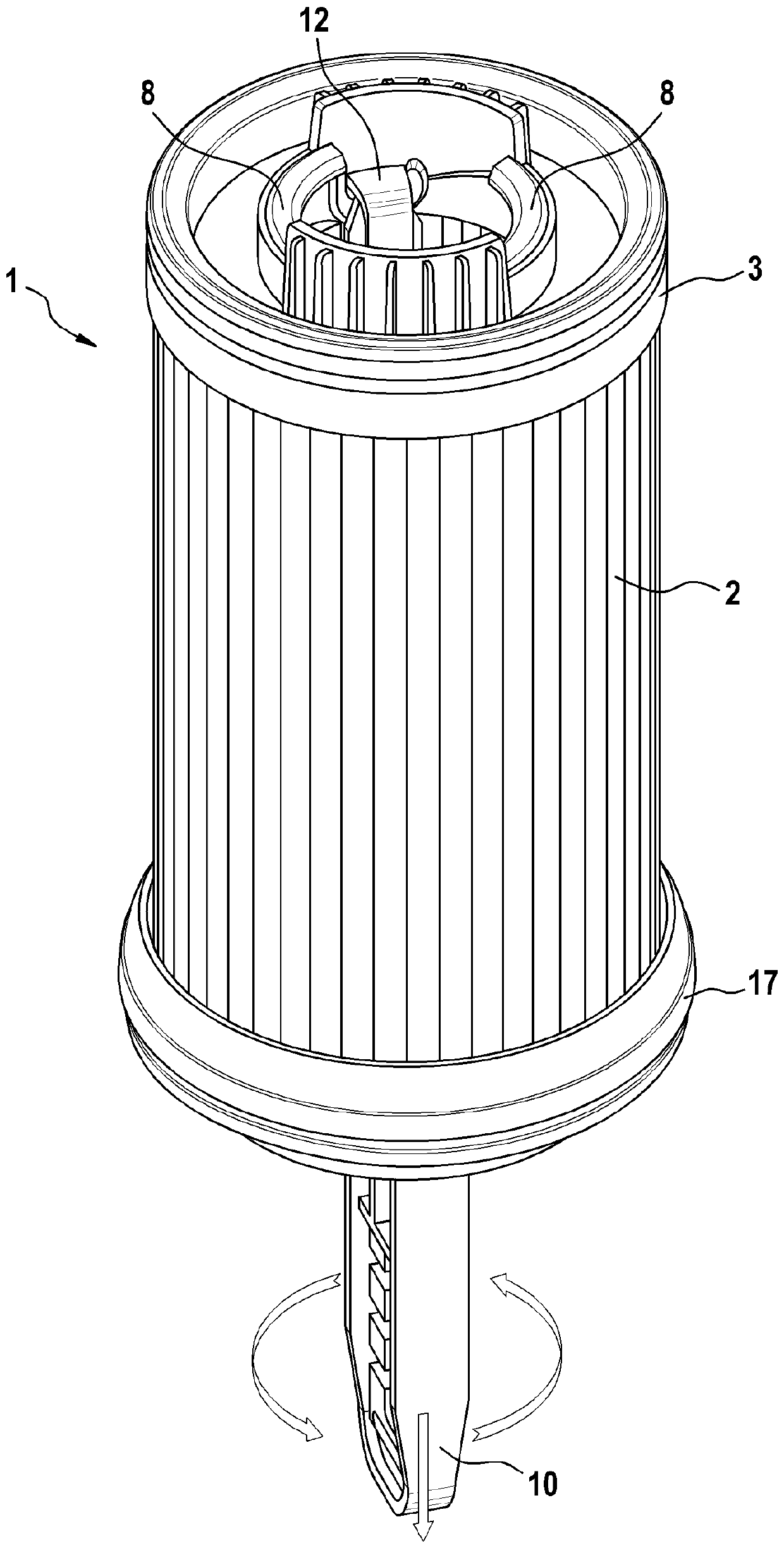
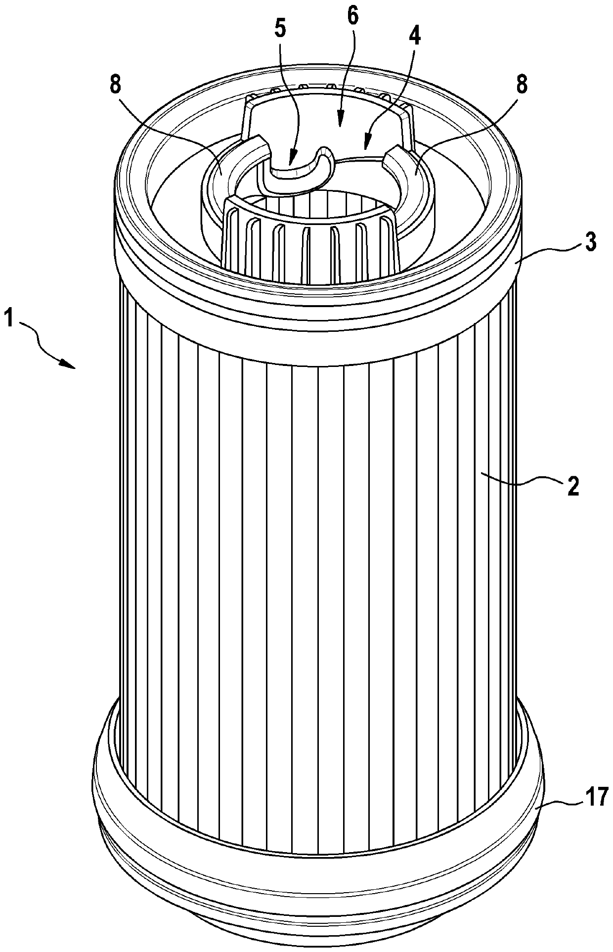
[0025] figure 1 A filter element 1 according to an exemplary embodiment of the invention is shown. The filter element 1 comprises a filter body 2 and an annular closure cap 3 . The closure cap 3 is arranged at the axial end of the filter body 2 , wherein the filter body 2 has a hollow-cylindrical shape, which is designed here as a cylinder. Accordingly, all directional statements regarding the hollow cylinder are indicated below.

[0026] Furthermore, the filter element 1 has an additional second closure cap 17 which is arranged axially on the end of the filter body 2 opposite the closure cap 3 . The additional second closure cap 17 is not considered further within the scope of the present invention. In particular, it is only provided that the additional second closure bell 17 is annular and has an inner diameter which at least corresponds to the largest inner diameter of the closure bell 3 . In the exemplary embodiment shown, the filter element 1 has no support tube in th...


PUM


Abstract

The invention relates to a filter element comprising a hollow filter body and at least one closure cap which is arranged on an axial end of the filter body, wherein the closure cap has a first A threading region of an inner diameter and a mating region having a second inner diameter, wherein the first inner diameter is greater than the second inner diameter, and wherein a tool can be passed through the threading region and can be The fitting area is fitted with the closure cover.

Description

technical field [0001] The invention relates to a filter element which can be used in particular in liquid filters, for example in fuel filters or urea filters. Background technique [0002] Liquid filters, in particular urea filters, are known from the prior art. These liquid filters are usually made of unstable materials such as paper. The filter body generally has a hollow cylindrical shape and is provided with a closure cap. If the filter is used, for example, on a vehicle, the filter is located inside a housing, wherein the enclosure seals the filter relative to the housing so that liquid can reach the filter in the inner space of the filter body for subsequent filtration through the filter body in order to exit the housing again on the circumference. [0003] If the filter is to be removed from the housing, there is the risk that the filter body is damaged and broken, so that only a part of the filter can be removed. The parts that remain in the housing must then b...

Claims


Application Information

Patent Timeline
Patent Type & Authority Patents(China)
IPC IPC(8): B01D29/15B01D29/96B25B27/00
CPCB01D29/15B01D29/96B25B27/0042B01D2201/24B01D2201/291B01D2201/305B01D2201/4015B01D2201/4084B01D2201/4053
Inventor M.卡斯特琼洛佩斯J.L.阿里亚斯阿里亚斯D.艾萨帕拉
Owner ROBERT BOSCH GMBH
Learn More