
Zero-tension taping machine main shaft structure

A tape wrapping machine, zero tension technology, applied in the direction of electrical components, circuits, cable/conductor manufacturing, etc., to ensure stable results

Pending Publication Date: 2020-09-08
杭州众业鑫科技有限公司
View PDF0 Cites 0 Cited by
  • Summary
  • Abstract
  • Description
  • Claims
  • Application Information

AI Technical Summary

Problems solved by technology

[0002] With the application of 5G technology and high-end software including cloud computing and big data; information communication and network equipment; the Internet of Things and the application of new generation information technology in smart cities, network information security, etc., ordinary 40G QSFP components can no longer meet the rapid development. High-speed communication needs, 100Gbps QSFP, 200Gbps QSFP-DD and other high-speed lines came into being. Their ultra-high transmission speed requires higher stability of electrical characteristics, and higher requirements for the stability and precision of production equipment. In order to solve this problem, there is an urgent need A Zero Tension Active Spinning Spindle Structure

Method used

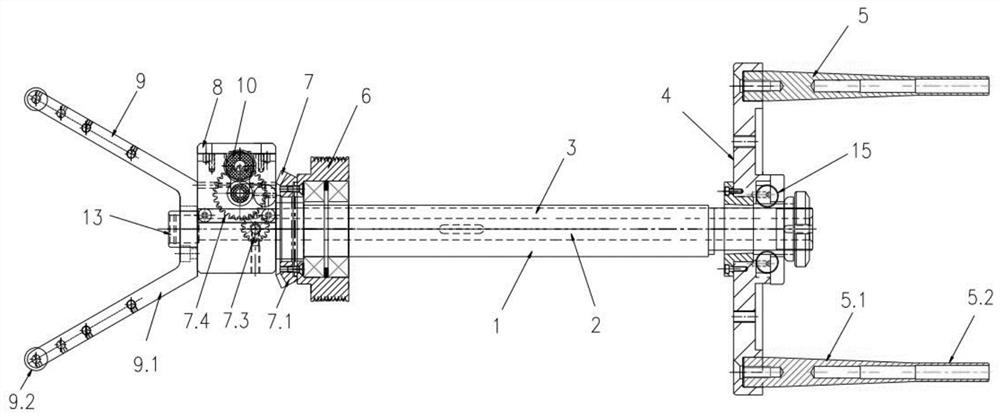
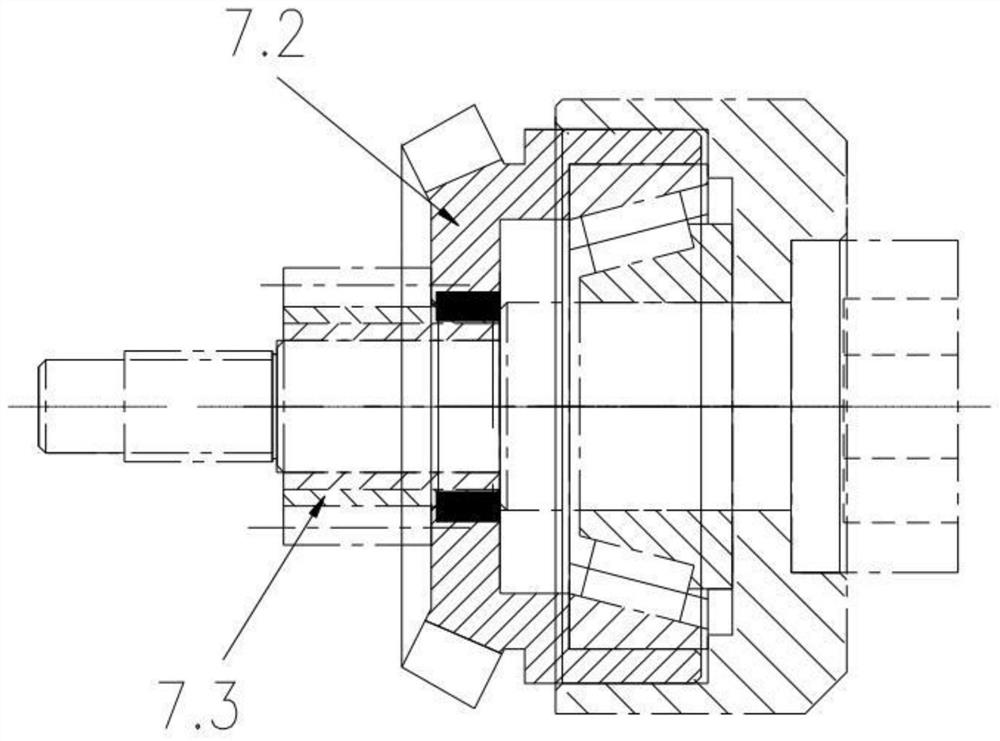
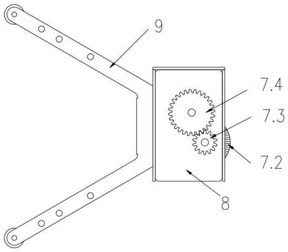

Image

  • Zero-tension taping machine main shaft structure
  • Zero-tension taping machine main shaft structure
  • Zero-tension taping machine main shaft structure

Examples


Embodiment Construction

[0019] combined with figure 1 , a main shaft structure of a zero-tension taping machine, comprising a main shaft 1, a central rod 2 arranged in the center of the main shaft 1, and a wire slot 3 arranged on one side of the central rod 2, and the outer end of the main shaft 1 is provided with a lead wire structure , the other end is provided with an outlet structure, the lead structure includes a disc body 4 arranged at the end of the main shaft 1, the side of the disc body 4 away from the main shaft 1 is provided with several wire passing rods 5 along the circumference, the outlet structure Sleeved on the other end of the main shaft 1 and flexibly connected with the main shaft 1, the outlet structure includes a multi-groove pulley 6, a bevel tooth assembly 7, a head assembly 8, and a horn assembly 9 arranged in sequence from the lead end to the outlet end. The multi-groove pulley 6 is movably arranged on the main shaft 1 through bearings, and is driven by an independent motor. ...


PUM


Abstract

The invention discloses a zero-tension taping machine main shaft structure. The structure comprises a main shaft, a central rod arranged in the center in the main shaft, and a wire passing groove formed in one side of the central rod, a lead structure is arranged at one end outside the main shaft, a wire outlet structure is arranged at the other end of the shell, the lead structure comprises a disc body arranged at the end part of the main shaft, a plurality of wire passing rods are arranged on one side of the disc body in the circumferential direction, the wire outlet structure comprises a multi-groove pulley, a bevel gear assembly, a machine head assembly and an ox horn assembly which are sequentially arranged from the wire leading end to the wire outlet end. According to the invention,through combined arrangement of the lead structure and the wire outlet structure, wrapping tape transfer and active tape releasing can be completed, and the wire passing rods with smooth mirror surfaces can overcome the defects of too large friction and unstability of a static rod of an original taping machine; by arranging the ox horn assembly, bounce caused by air cutting of the wrapping tape during high-speed rotation can be reduced, and the stability of the wrapping tape is ensured; through the arrangement of a wire leading wheel, a driving wheel and a rubber pressing wheel, the wrapping tape is transferred in a friction mode, and no deformation of the wrapping tape wire is guaranteed in the transferring process.

Description

technical field [0001] The invention relates to the technical field of taping machines, in particular to a zero-tension taping machine spindle structure. Background technique [0002] With the application of 5G technology and high-end software including cloud computing and big data; information communication and network equipment; the Internet of Things and the application of new generation information technology in smart cities, network information security, etc., ordinary 40G QSFP components can no longer meet the rapid development. High-speed communication needs, 100Gbps QSFP, 200Gbps QSFP-DD and other high-speed lines came into being. Their ultra-high transmission speed requires higher stability of electrical characteristics, and higher requirements for the stability and precision of production equipment. In order to solve this problem, there is an urgent need A zero-tension active unwinding belt spindle structure. Contents of the invention [0003] In order to solve ...

Claims


Application Information

Patent Timeline
Patent Type & Authority Applications(China)
IPC IPC(8): H01B13/26
CPCH01B13/26H01B13/262H01B13/2626
Inventor 陈子华沈伟锋周苏东
Owner 杭州众业鑫科技有限公司
Learn More