Water level control valve with flow rate continuous control function

A technology of water level control and flow, applied in the direction of sliding valves, valve details, valve devices, etc., can solve the problem of inability to accurately control the water output of the valve, achieve less instability, sensitive valve action, and overcome the friction of the valve core Effect

Inactive Publication Date: 2012-03-21
ZHEJIANG IND POLYTECHNIC COLLEGE
View PDF5 Cites 5 Cited by
  • Summary
  • Abstract
  • Description
  • Claims
  • Application Information

AI Technical Summary

Problems solved by technology

[0003] Aiming at the problem that the current water level control valve cannot accurately control the water output of the valve, the present invention proposes a water level control valve with the function of continuous flow control

Method used


Image

  • Water level control valve with flow rate continuous control function
  • Water level control valve with flow rate continuous control function
  • Water level control valve with flow rate continuous control function

Examples


Embodiment Construction

[0019] Further illustrate the present invention below in conjunction with accompanying drawing

[0020] Referring to the attached picture:

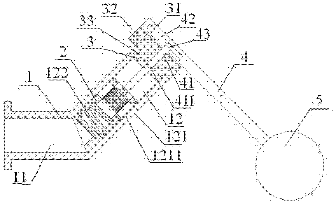
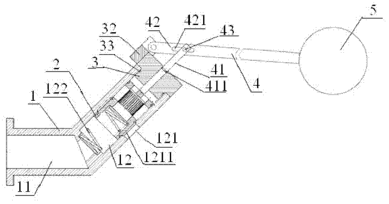
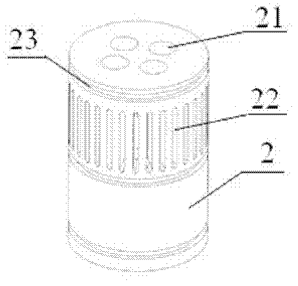
[0021] The water level control valve with continuous flow control function according to the present invention includes a valve body 1, a valve core 2, a valve body cover 3, a float connection device 4, and a float 5, and the valve body 1 is provided with a water inlet chamber 11 . The water outlet chamber 12, the side wall of the water outlet chamber 12 is provided with a water outlet hole 121, and a return spring 122 is installed inside the end connected to the water inlet chamber 11, the valve core 2 is placed inside the water inlet chamber 11, The end of the return spring 122 is inserted into the water inlet end of the spool 2; the water inlet end of the spool 2 is provided with a step hole 21 cooperating with the return spring, and a balance hole 22 is provided on the water outlet end; the valve The body cover 3 is provided with a ce...


PUM


Abstract

The invention discloses a water control valve with a flow rate continuous control function. The water level control valve comprises a valve body, a valve core, a valve body cover, a floating ball connecting device and a floating ball, wherein the water body is provided with a water inlet cavity and a water outlet cavity; a water outlet hole is formed in the side wall of the water outlet cavity; areturning spring is arranged in one end, connected with the water inlet cavity, of the water outlet cavity; the valve core is arranged in the water inlet cavity; a step hole matched with the retuningspring is arranged at the water inlet end of the valve core; a balance hole is formed in a water outlet end surface; the valve body cover is provided with a centre hole and a floating ball rod seat; the floating ball connecting device comprises a valve core mandrill and a floating ball rod; one end of the valve core mandrill passes through the centre hole to contact the valve core; and the other end of the valve core is connected with the floating ball rod. The water level control valve with the flow rate continuous control function has the advantages that: the flow rate at a valve port can change continuously according to the water level in a water pool; the water inlet cavity and the water outlet cavity form a 45-degree structure, so that the dead weight of the floating ball and the floating ball rod overcomes the frictional force of the valve core; therefore, the action of the valve is more flexible and reliable.

Description

technical field [0001] The invention relates to a water level control valve with a continuous flow control function, which belongs to the field of electromechanical equipment. Background technique [0002] At present, whether the water level control valves provided on the market are mechanical or electronic, they are basically switch control methods. The valve is in two states of "on" and "off", and can only control the water level in two states of "high" and "low". situation. In some special occasions with high water level control requirements, it is necessary to control the water output of the valve to adapt to the continuous change of water level. Therefore, it is an important research topic to develop a water level control valve with the function of continuous flow control. Contents of the invention [0003] Aiming at the problem that the current water level control valve cannot accurately control the water output of the valve, the invention proposes a water level co...

Claims


Application Information

Patent Timeline
Patent Type & Authority Applications(China)
IPC IPC(8): F16K41/02F16K31/30F16K3/30
Inventor 刘健吴雄喜高奇峰
Owner ZHEJIANG IND POLYTECHNIC COLLEGE
Why Eureka
Try Eureka