Supercharge Your Innovation With Domain-Expert AI Agents!

Tool coupling arrangement for drills and reamers

A coupling device and tool technology, applied in reamers, manufacturing tools, drilling tool accessories, etc., can solve the problems of not being able to reinforce the tapered seat and affecting discarding

Active Publication Date: 2018-01-02
ISCAR LTD
View PDF15 Cites 1 Cited by
  • Summary
  • Abstract
  • Description
  • Claims
  • Application Information

AI Technical Summary

Problems solved by technology

In other words, it may be difficult to make the angle small enough to improve accuracy, or too large to reinforce the tapered seat
In addition, the length of the coupling area (also affected by the aforementioned angles) is short compared to the diameter measured at the opening or end face of the tapered seat, which can adversely affect discard during processing

Method used


Image

  • Tool coupling arrangement for drills and reamers
  • Tool coupling arrangement for drills and reamers
  • Tool coupling arrangement for drills and reamers

Examples


Embodiment Construction

[0030] In the following description, various aspects of the subject matter of the present application will be described. For the purpose of illustration, specific configurations and details are explained in sufficient detail to provide a thorough understanding of the subject matter of this application. However, it is obvious to those skilled in the art that the subject matter of the present application can be implemented without the specific configuration and details given herein.

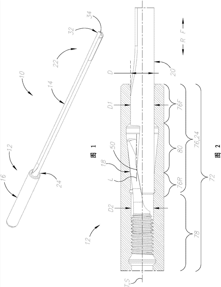
[0031] Reference figure 1 with figure 2 . The drill bit 10 has a coupling device 12, which includes a tool portion 14 and a shank portion 16, which are coupled together by an internal, elongated coupling member 18. The assembled drill bit 10 defines the front to back direction (F, R), which is figure 2 Defined by arrows. To assemble the drill bit 10, the tool part 14 is axially inserted into the shank part 16 until the coupling device 12 reaches the assembly position. Then, the tool part 14 is ax...


PUM


Abstract

A tool coupling arrangement (12) for drills and reamers includes tool and shank portions (14,16) with respective tool and shank axial stoppers (46,48). An at least partially cylindrical tool couplingend (24) of the tool portion (14) is located within a longitudinal through forward bore portion (76) in the shank portion (16), and is coupled therein via an elongated coupling member (18), which is located further inwards in the shank portion (16) and comprises axially opposite member coupling and pulling ends (56,58). The forward bore portion (76) has front and rear sub-portions (76F,76R) and abore recess (80) which is located therebetween and extends radially outwardly. In a locked position (figures 3 to 6), the tool axial stopper (46) abuts the shank axial stopper (48). The tool couplingend (24) abuts the front and rear sub-portions (76F,76R) and coupling end (56) of the coupling member (18) is wedged between the tool coupling end (24) and the bore recess (80).

Description

Technical field [0001] The subject of this application relates to tools, such as drill bits and reamers, and particularly to the axial coupling device between the two parts of the drill bit or reamer. Background technique [0002] US6976815 discloses a milling cutter, which includes a main body with three cutting edges formed by the main body. The end of the main body, which is arranged opposite to the cutting edge, defines the fastening end of the milling cutter. The milling cutter includes a first tapered shank with a hook-shaped coupling portion, which includes a first shoulder and a first groove. The milling cutter also includes a second tapered portion provided with a second coupling portion, and the second coupling portion is used to cooperate with the first coupling portion. Inside the second coupling part, in the axial direction, the locking screw has an externally threaded, preferably cylindrical part. This coupling device is based on the concept of a tapered surface ...

Claims


Application Information

Patent Timeline
Patent Type & Authority Applications(China)
IPC IPC(8): B23B31/00B23B51/04B23B51/06B23D77/00B23D77/02
CPCB23B51/0486B23B2251/02B23B31/005B23B2231/0204B23D2277/02B23D77/006B23B51/066B23B51/06B23B51/12B23D77/02B23D2277/06B23B2250/12B23D2277/60
Inventor 吉尔·赫克特
Owner ISCAR LTD
Features
  • R&D
  • Intellectual Property
  • Life Sciences
  • Materials
  • Tech Scout
  • Unparalleled Data Quality
  • Higher Quality Content
  • 60% Fewer Hallucinations
Learn More