Battery terminal and method for producing a battery terminal

A battery and terminal technology, applied in the direction of conductive connection, electrical connection seat, electrical component connection, etc., can solve the problem of difficult access to spiral devices, and achieve the effects of good accessibility, reduced complexity, and reduced geometric complexity.

Active Publication Date: 2018-01-02
海拉有限双合股份公司
View PDF6 Cites 0 Cited by
  • Summary
  • Abstract
  • Description
  • Claims
  • Application Information

AI Technical Summary

Problems solved by technology

This configuration has the disadvantage that the helical device is difficult to access

Method used


Image

  • Battery terminal and method for producing a battery terminal
  • Battery terminal and method for producing a battery terminal
  • Battery terminal and method for producing a battery terminal

Examples


Embodiment Construction

[0023] Identical or functionally identical components are provided with the same reference symbols in the various figures.

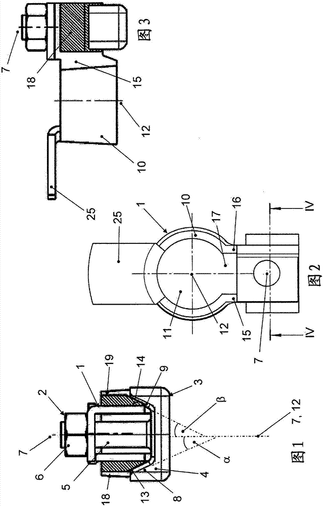
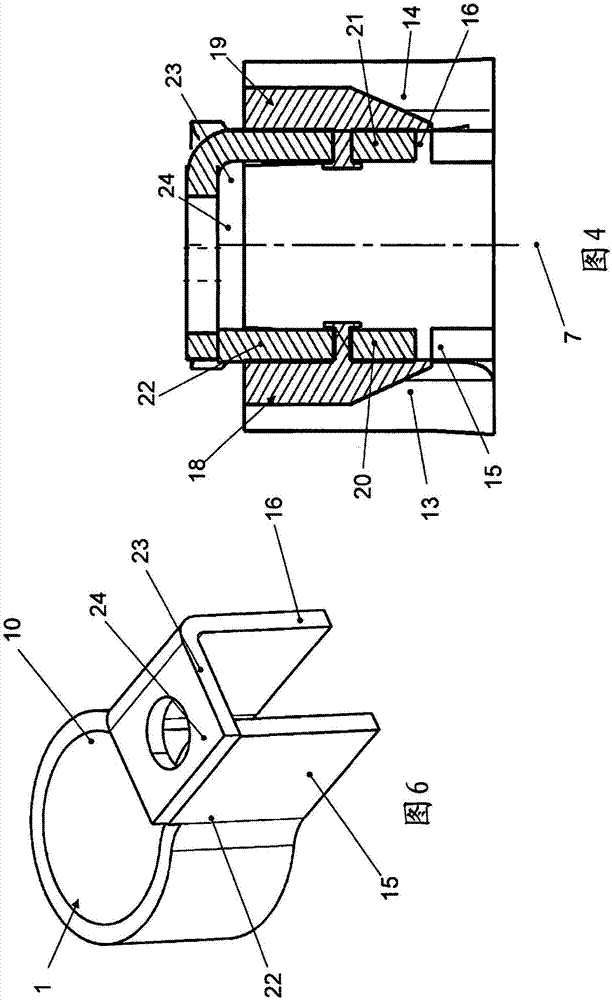
[0024] battery terminal Figure 1 to Figure 4 The embodiment shown in includes a one-piece stamped and bent part 1 and a screw element 2 . The screw element 2 comprises a bolt 3 with a head 4 and a threaded section 5 and a nut 6 into which the threaded section 5 can be screwed. The cylinder axis 7 of the threaded section 5 is at figure 1 , figure 2 and image 3 drawn in.

[0025] The stamped and bent part 1 is at least partially produced from an electrically conductive material, in particular a metal, for example copper or a copper alloy.

[0026] On the side of the head 4 facing the threaded section 5, two opposite inclined surfaces 8, 9 are provided, which are aligned with the axial direction of the threaded section 5 or its cylinder. The axis 7 forms an angle α, which in the illustrated embodiment is between 10° and 40°, in particular between 2...


PUM


Abstract

The invention relates to a battery terminal, comprising a stamped and bent part (1) on which a seat (10) is formed and can be applied to a pole of a battery in an application direction, screw means (2) for the clamping attachment of the seat (10) to the pole of the battery, wherein said screw means (2) can be actuated or screwed in substantially in the application direction of the seat (10), and clamping means which cooperate with the screw means (2) for the clamping attachment of the seat (10) to the pole of the battery, the clamping means comprising at least one clamping element (18, 19) which is connected to and / or rests against the stamped and bent part (1).

Description

technical field [0001] The invention relates to a battery terminal according to the preamble of claim 1 and to a method for producing such a battery terminal. Background technique [0002] A battery terminal of the aforementioned type is known from EP1675221A1. The battery terminal described therein comprises a receptacle which can be pushed onto one pole of the battery and a screw means for clamping the receptacle to the pole of the battery. The screw means here comprises a screw which can be inserted into a nut, wherein the screw can be screwed in the mounting direction of the receptacle or in the longitudinal direction of the pole. Said direction generally corresponds to the vertical direction, so that in this type of battery terminal, said fastening is also referred to as vertical bolting. In EP 1 675 221 A1 the receptacle is formed on the first stamped and bent part. The battery terminal comprises two further stamped and bent parts which can be inserted laterally int...

Claims


Application Information

Patent Timeline
Patent Type & Authority Applications(China)
IPC IPC(8): H01R11/28
CPCH01R11/283Y02E60/10
Inventor K·齐默尔曼M·翁特哈尔特
Owner 海拉有限双合股份公司
Why Eureka
Try Eureka