Punching die

A punching die, punching punch technology, used in punching tools, metal processing equipment, manufacturing tools, etc.

Inactive Publication Date: 2018-01-05
天津市世纪海达机械设备制造有限公司
View PDF0 Cites 0 Cited by
  • Summary
  • Abstract
  • Description
  • Claims
  • Application Information

AI Technical Summary

Problems solved by technology

After one stroke is completed, the punch feeder moves the material forward according to a fixed step distance, so that multiple processes can be completed on a pair of molds, but the existing punching progressive dies are difficult in punching and unloading. Flawed and needs to be improved

Method used


Image

  • Punching die

Examples


Embodiment Construction

[0011] Below, the substantive features and advantages of the present invention will be further described in conjunction with examples, but the present invention is not limited to the listed examples.

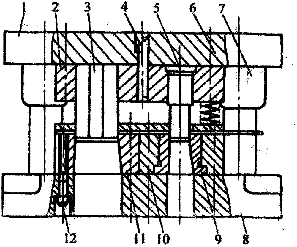
[0012] see figure 1 , which shows the structure of a punching die provided by the embodiment of the present invention. For the convenience of description, only the parts related to the embodiment of the present invention are shown.

[0013] See figure 1 , a punching die, including an upper die and a lower die connected to the upper die through a guide post and guide sleeve assembly 7, the upper die includes an upper die base 1 and a protrusion fixed on the upper die base Die 3, punching punch 5, described punch 3 is installed on the described upper mold base 1 by punch fixing plate 2, described lower mold comprises lower mold base 8 and is located on the corresponding corresponding parts on described lower mold base 8 respectively The punching die 9 and the die 11 of the punch...


PUM


Abstract

The invention relates to a punching die, which includes an upper die and a lower die connected to the upper die through a guide post and guide sleeve assembly, the upper die includes an upper die base and a protrusion fixed on the upper die base Die, punching punch, described punch is installed on the described upper mold base through punch fixing plate, described lower mold comprises lower mold base and is located on described lower mold base and is respectively corresponding to described punching punch, punch punching die and die, the die is installed on the lower die base through the die fixing plate, the upper die base is hung with a discharge screw, and the discharge screw is provided with a discharge screw spring. The progressive punching die of the present invention can realize effective punching, and unloading after punching is conveniently carried out through the unloading screw and the unloading spring.

Description

technical field [0001] The invention belongs to the technical field of moulds, and in particular relates to a structurally improved progressive punching die. Background technique [0002] The progressive die is composed of multiple stations, and each station is connected in sequence to complete different processing, and a series of different stamping processes are completed in one stroke of the punching machine. After one stroke is completed, the punch feeder moves the material forward according to a fixed step distance, so that multiple processes can be completed on a pair of molds, but the existing punching progressive dies are difficult in punching and unloading. There are flaws and needs to be improved. Contents of the invention [0003] The object of the present invention is to solve the above technical problems and provide a structurally improved progressive punching die. [0004] To achieve the above object, the present invention adopts the following technical sol...

Claims


Application Information

Patent Timeline
Patent Type & Authority Applications(China)
IPC IPC(8): B21D28/34B21D45/06
Inventor 李淑海
Owner 天津市世纪海达机械设备制造有限公司
Why Eureka
Try Eureka