Infrared detection device
A detection device, infrared technology, applied in the direction of measuring devices, optical device exploration, electric radiation detectors, etc., can solve the problems of image stripes or jagged, image noise, etc., to achieve the effect of suppressing image distortion
- Summary
- Abstract
- Description
- Claims
- Application Information
AI Technical Summary
Problems solved by technology
Method used
Image
Examples
Embodiment approach 1
[0125] [Structure of infrared detection device]
[0126] Hereinafter, an infrared detection device according to Embodiment 1 will be described with reference to the drawings.
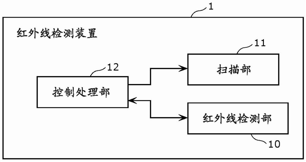
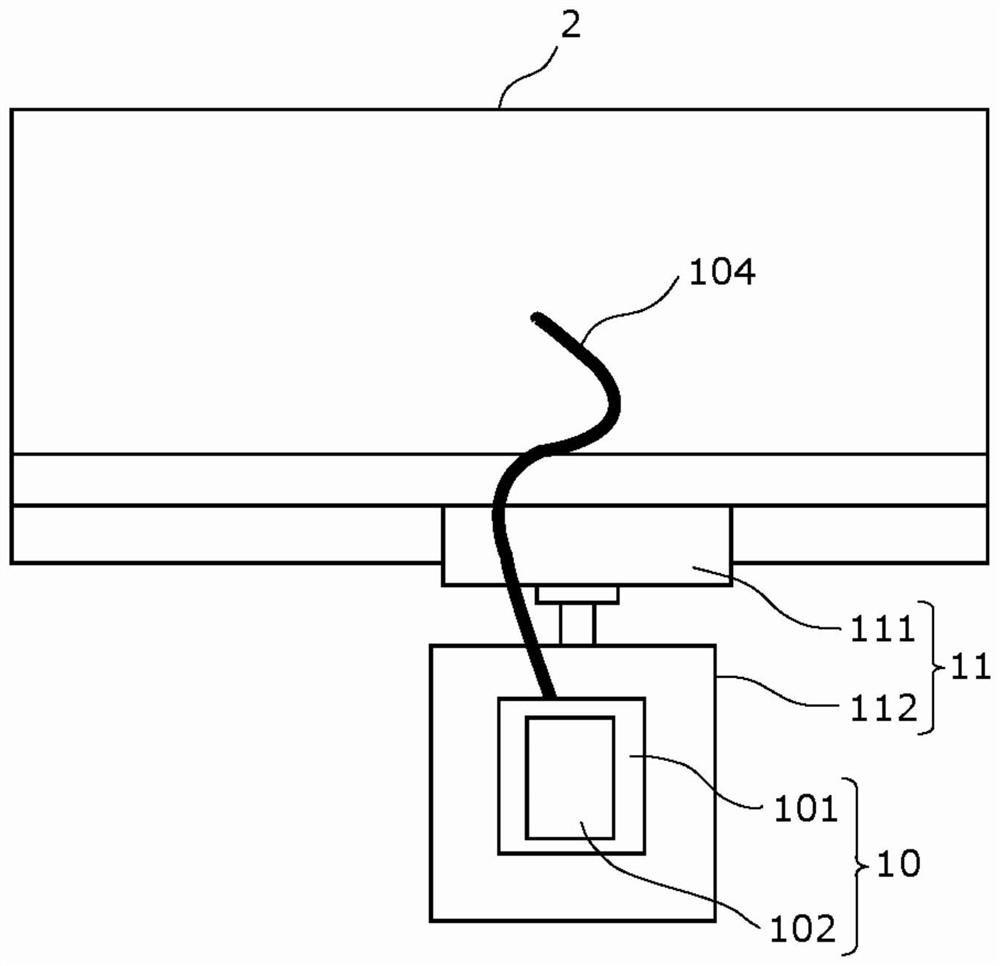
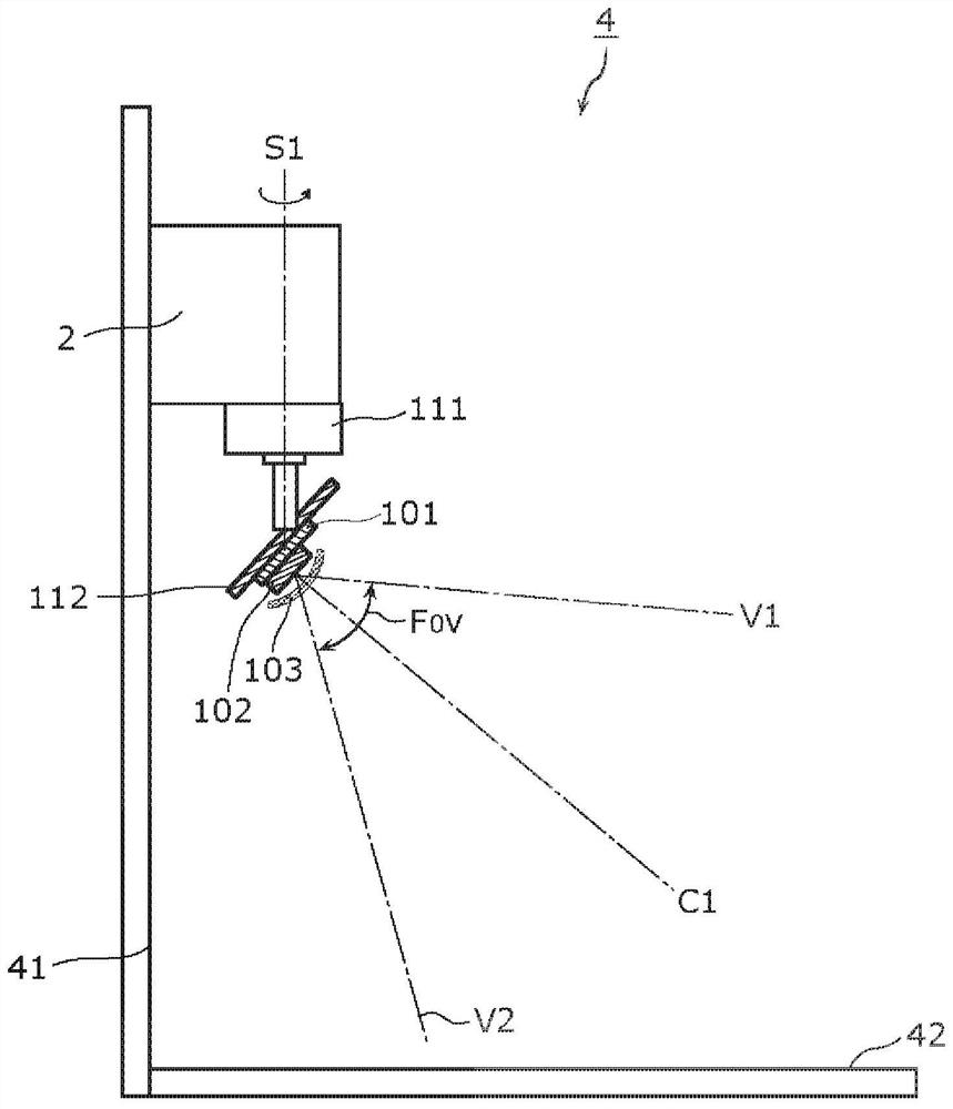
[0127] figure 1 It is a figure which shows an example of the structure of the infrared detection apparatus of Embodiment 1. figure 2 It is a schematic diagram of the physical structure when the infrared detection device of this embodiment is mounted in a housing|casing. image 3 It is a figure which shows the state where the housing|casing mounted with the infrared detection device of this embodiment is installed. Figure 4 It is a figure which shows the physical structure of the infrared detection apparatus of this embodiment.
[0128] Such as image 3As shown, the infrared detection device 1 is installed on the frame body 2 to obtain a thermal image of the detection object range. The frame body 2 is installed on the installation surface 41 approximately perpendicular to the bottom surface 42 of t...
Embodiment approach 2
[0151] In Embodiment 1, it has been described that the distortion correction process is performed on the distortion of the thermal image output by the infrared sensor 102 by the control processing unit 12 , but the present invention is not limited thereto. By considering the inclination of one or more infrared detection elements constituting the infrared sensor 102 with respect to the scanning rotation axis S1 , it is unnecessary to perform distortion correction processing in the control processing unit 12 . This case will be described below.
[0152] Figure 6 It is a figure for explaining that distortion occurs in the thermal image scanned by the infrared sensor of Embodiment 1.
[0153] When the infrared sensor 102 rotates around the scanning rotation axis S1 , the rotational speeds (rotation pitch) of the upper end and the lower end of the infrared sensor 102 viewed from the bottom surface 42 are different. For example, it is assumed that the infrared sensor 102 is compo...
Deformed example 1
[0175] Figure 10 It is a figure which shows an example of the structure of the infrared sensor of the modification 1 of Embodiment 2.
[0176] exist Figure 9 In the infrared sensor 202b shown, the case where the interval between adjacent columns, that is, the center and pitch of corresponding infrared detection elements in adjacent columns are constant, has been described, but the present invention is not limited thereto. Such as Figure 10 As shown in the infrared sensor 202c, the centers and pitches of the corresponding infrared detection elements in adjacent columns may also be formed to be narrower as they get closer to the bottom surface 42 . That is, it can also be: Figure 10 In the shown infrared sensor 202c, a plurality of infrared detection elements are arranged in three or more rows, and the width of each of the plurality of infrared detection elements in each row of the arrangement is substantially parallel to the bottom surface 42. The position of each of th...
PUM
 Abstract
Description
Claims
Application Information
 - R&D
- Intellectual Property
- Life Sciences
- Materials
- Tech Scout
- Unparalleled Data Quality
- Higher Quality Content
- 60% Fewer Hallucinations
Browse by: Latest US Patents, China's latest patents, Technical Efficacy Thesaurus, Application Domain, Technology Topic, Popular Technical Reports.
© 2025 PatSnap. All rights reserved.Legal|Privacy policy|Modern Slavery Act Transparency Statement|Sitemap|About US| Contact US: help@patsnap.com


