Bearing pressure load test equipment

A technology of load testing and bearing pressure, applied in the direction of mechanical bearing testing, etc., can solve the problems of high cost and long time, achieve the effect of simple and convenient installation, reduce jitter, and prevent damage

A technology of load testing and bearing pressure, applied in the direction of mechanical bearing testing, etc., can solve the problems of high cost and long time, achieve the effect of simple and convenient installation, reduce jitter, and prevent damage

CN107543701AInactive Publication Date: 2018-01-05WUXI SIBORUI ELECTROMECHANICAL CO LTD

Image

  • Bearing pressure load test equipment
  • Bearing pressure load test equipment

Examples


Embodiment Construction

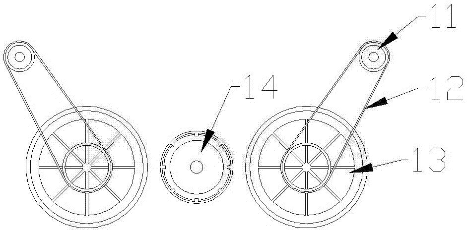
[0021] The present invention is described in further detail now in conjunction with accompanying drawing. These drawings are all simplified schematic diagrams, which only illustrate the basic structure of the present invention in a schematic manner, so they only show the configurations related to the present invention.

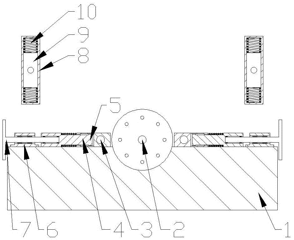
[0022] Such as figure 1 and figure 2 As shown, the present invention is a kind of bearing pressure load testing equipment, including a machine base, a bearing fixing seat is fixed in the middle of the machine base, the fixed axis of the bearing fixing seat is parallel to the surface of the loading table of the machine base, and A torque tester is fixed on the bearing holder, and a bearing inner frame clamp is fixed on the torque input shaft of the torque tester;

[0023] A thrust rod mechanism is arranged symmetrically on both sides of the corresponding bearing fixing seat on the stage;

[0024] The thrust rod mechanism includes a threaded seat fixed on th...


PUM


Abstract

The invention relates to a bearing pressure load testing device, which includes a machine base, a bearing fixing seat is fixed in the middle of the machine base, a torque tester is fixed on the bearing fixing seat, and a bearing inner shaft is fixed on the torque input shaft of the torque tester. Frame clamp; a thrust rod mechanism is symmetrically arranged on both sides of the corresponding bearing fixing seat on the stage; the thrust rod mechanism includes a threaded seat fixed on the surface of the stage and a push block slidingly connected with the surface of the stage. The threaded seat is connected with a push rod, and the end of the push rod is connected with the push block; two motor seats are symmetrically arranged on the upper part of the machine base, and the motor seat includes a guide slide rail, and a motor fixing block is slidably connected in the guide slide rail. The motor is vertically fixed on the motor fixing block, and the two axial sides of the motor fixing block are elastically connected with the two ends of the guide rail; the output shaft of the motor is provided with a drive wheel, which is connected by rotation on the push block. There is a traction wheel, and the traction wheel and the driving wheel are connected through a belt drive.

Description


Claims


Application Information

Patent Timeline
05 Jan 2018
Publication
CN107543701A