Automatic landing method of unmanned aerial vehicle based on visual guidance

An automatic landing, vision-guided technology, applied in the field of drones and machine vision, can solve the problems of inability to achieve precise landing of drones, unsuitable for loading, and high price, and achieve the goal of improving intelligence, improving accuracy, and reducing interference. Effect

Active Publication Date: 2018-01-05
XIDIAN UNIV
View PDF7 Cites 25 Cited by
  • Summary
  • Abstract
  • Description
  • Claims
  • Application Information

AI Technical Summary

Problems solved by technology

However, at present, the autonomous landing of UAVs mostly uses GPS navigation and positioning. The GPS system for precise positioning is expensive and bulky, and is not suitable for loading on UAVs; the positioning accuracy of civilian GPS can only reach within 10 meters. , this accuracy cannot meet the requirements of precise landing of drones

Method used


Image

  • Automatic landing method of unmanned aerial vehicle based on visual guidance
  • Automatic landing method of unmanned aerial vehicle based on visual guidance
  • Automatic landing method of unmanned aerial vehicle based on visual guidance

Examples


Embodiment 1

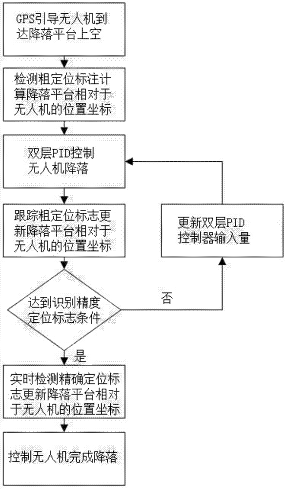
[0053] In order to improve the accuracy of the autonomous landing of UAVs, the present invention provides a method for automatic landing of UAVs based on vision guidance, such as figure 1 Shown, the realization steps of the present invention are as follows:

[0054] Including the following steps:

[0055] Step 1) According to the GPS information of the landing platform, guide the UAV to enter the sky above the landing platform through GPS navigation, and then lower the height of the UAV so that the UAV hovers at a distance of 10-15m from the ground;

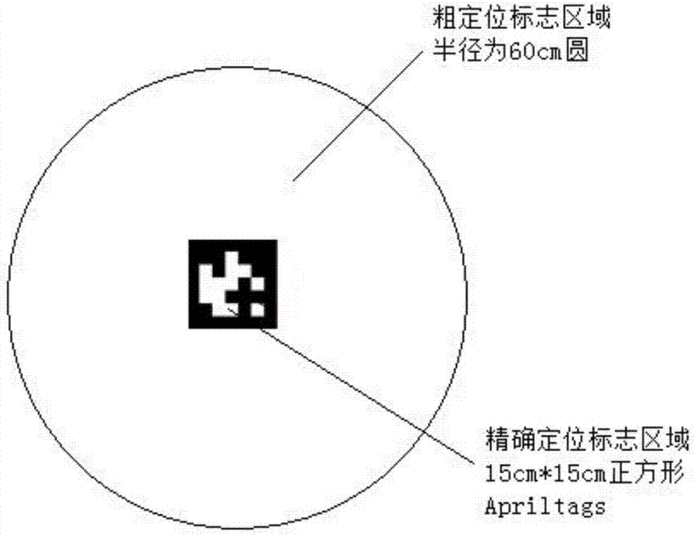
[0056] Among them, the landing platform is a plane marked with a landing sign, such as figure 2 As shown, the landing mark is composed of a precise positioning mark and a coarse positioning mark at the same point in the center, the precise positioning mark is a square Apriltags with a side length of 15cm, and the rough positioning mark is the area between the circle and the Apriltags with a radius of 60cm, The coarse locator a...

Embodiment 2

[0082] In order to verify the effectiveness and feasibility of the present invention, this example controls the UAV to hover at a height of 12m from the ground, and then performs the autonomous landing of the UAV under visual guidance. In the initial state, the coarse positioning detected by the UAV signs such as Figure 5a , Figure 5b , Figure 5c shown, where Figure 5a Images captured by drone cameras, Figure 5b is the area where the rough positioning mark is located after the binarized image, Figure 5c The box in represents the area of ​​the detected coarse positioning mark. The center coordinates of the landing platform calculated by the coarse positioning mark are: (252, 341) in pixels, and the calculated position coordinates of the landing platform relative to the UAV (X, Y , h) is: (4.2, 1.9, 12) and the unit is m.

[0083] During the landing process of the UAV, the coarse positioning mark is automatically tracked, and the position coordinates (X, Y, h) of the ...


PUM


Abstract

The invention discloses an automatic landing method of an unmanned aerial vehicle based on visual guidance. The implementation scheme comprises the steps that 1, the unmanned aerial vehicle is guidedby GPS navigation to get to the sky above a landing platform; 2, a coarse positioning mark is detected according to an image shot by an airborne camera, and position coordinates of the landing platform relative to the unmanned aerial vehicle are calculated; 3, the unmanned aerial vehicle is controlled by an unmanned aerial vehicle double-layer PID controller to start descending; 4, the position coordinates of the landing platform relative to the unmanned aerial vehicle are updated, and thus the input of the double-layer PID controller is updated; and 5, when the unmanned aerial vehicle descends to reach a condition of recognizing an accurate positioning mark, real-time detection is performed by using an Apriltags technology to obtain new center coordinates of the landing platform, the input of the double-layer PID controller is updated, and accurate landing of the unmanned aerial vehicle is completed. The automatic landing method solves a problem of low GPS guided unmanned aerial vehicle landing accuracy and can be applied to accurate autonomous landing of the unmanned aerial vehicle.

Description

technical field [0001] The invention belongs to the field of unmanned aerial vehicles and machine vision, and specifically relates to an automatic landing method for unmanned aerial vehicles based on vision guidance, which can be used for autonomous landing of unmanned aerial vehicles at fixed locations. Background technique [0002] UAV (Unmanned Aerial Vehicle) is a kind of unmanned aerial vehicle, which has the advantages of convenient use, flexible maneuverability and intelligence. Aerial photography, disaster detection, pesticide spraying, etc.) have broad application prospects. Moreover, the rotor UAV also has the advantages of being able to take off and land vertically, hover in the air, and fly flexibly in any direction, and has received more and more attention in recent years. [0003] In order to reduce the cost, a basic requirement for the UAV system is that it should be safe and recyclable, that is, the UAV should be able to achieve safe and reliable recovery af...

Claims


Application Information

Patent Timeline
IPC IPC(8): G05D1/12
Inventor 孙伟郭宝龙赵春宇张琦刘润之郭振嘉王鹏飞陈许蒙
Owner XIDIAN UNIV
Why Eureka
Try Eureka