
Square cell clamp and ejection mechanism

A square cell and fixture technology, applied in circuits, electrical components, primary batteries, etc., can solve the problems of high positioning accuracy, scratches on the surface of the cell, and unevenness on the surface of the cell, reducing positioning accuracy requirements and changing models. handy effect

Active Publication Date: 2018-01-05
WUXI LEAD INTELLIGENT EQUIP CO LTD
View PDF4 Cites 8 Cited by
  • Summary
  • Abstract
  • Description
  • Claims
  • Application Information

AI Technical Summary

Problems solved by technology

[0003] There are many problems in the existing setting method: First, the cell will be filled with pressure gas during the liquid injection process, which will cause plastic deformation of the cell. Therefore, after the liquid injection is completed, the loading and unloading manipulator When grabbing the cell and pulling it out, there will be friction between the cell and the bushing, which will scratch the surface of the cell; secondly, since the side wall of the bushing has to reserve a space for the loading and unloading manipulator to grab, and during the liquid injection process , the battery cell will undergo plastic deformation again, which will make the surface of the battery cell uneven; moreover, since the battery cell cannot be deformed too much, when the battery cell 101 is put into the bush 100, the bush 100 and The gap between the cells 101 is not large, which requires high positioning accuracy of the loading and unloading manipulator

Method used

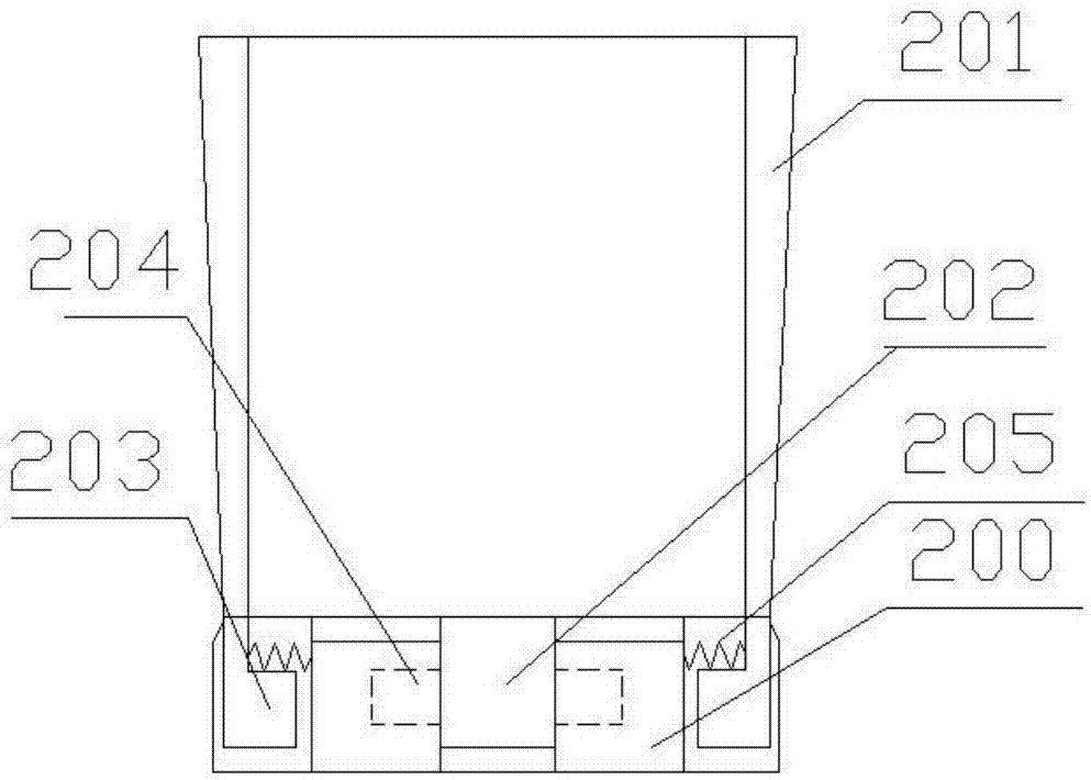
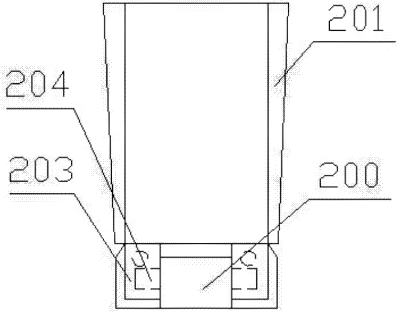
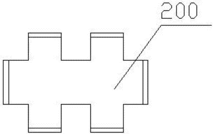

Image

  • Square cell clamp and ejection mechanism
  • Square cell clamp and ejection mechanism
  • Square cell clamp and ejection mechanism

Examples


Embodiment Construction

[0030] The present invention will be further described below in conjunction with specific drawings.

[0031] In the description of the following specific embodiments, the coordinates are referred to: figure 1 The up and down directions in the middle are up and down, the left and right directions are left and right, the direction perpendicular to the paper surface is back, and vice versa. In the specific embodiment of the present invention, the front-rear direction is the longitudinal direction, and the left-right direction is the horizontal direction.

[0032] In order to solve many problems in the prior art, the present invention discloses a square cell clamp and ejection mechanism, wherein the square cell clamp mainly includes two parts, a bushing part and a clamping part.

[0033] Among them, the bushing part such as figure 1 , figure 2 As shown, it mainly includes a bottom plate 200 and four side plates 201, and the four side plates 201 are rotatably arranged on the front, rea...


PUM


Abstract

The invention relates to a square cell clamp. The square cell clamp is characterized by comprising a lining part and a clamping part; a lining clamping region is arranged in the clamping part; the lining part is arranged in the lining clamping region of the clamping part; the lining part comprises a bottom plate and multiple side plates, and each side plate is rotationally arranged on the side part of the bottom plate separately; the cell is placed in a region formed by the bottom plate and the multiple side plates in a surrounding manner; the inner side surface of each side plate is a vertical surface matched with the side surface of the cell; the thickness of each side plate is decreased from the top to bottom gradually to form an inclined surface on the outer side surface of the side plate; a first hole is formed in the bottom of the clamping part; the lining part and the cell are jacked out of the clamping part by a lining ejection rod which penetrates through the first hole; a second hole corresponding to the first hole is formed in the bottom of the lining part; and the cell is jacked out of the lining part by a cell ejection rod which penetrates through the second hole. By adoption of the lining part and the clamping part which can be opened automatically, scraping of the cell surface caused by friction between the cell and the lining can be avoided.

Description

Technical field [0001] The invention relates to a square battery cell clamp and an ejection mechanism, belonging to the technical field of battery manufacturing equipment. Background technique [0002] When the existing square battery cell is injected, the battery cell 101 is put into a Figure 5 In the bushing 100 shown, the battery core 101 with the bushing 100 is then put into a clamping mechanism, the position of the battery core 101 is fixed, and then the battery is vacuumed and injected. The side of the bushing 100 is in the shape of "convex", and its two shoulder positions expose the two shoulders of the battery core 101. The exposed position of the battery core 101 is used for the loading and unloading manipulator to grab the battery core 101, and the purpose of setting the bushing 100 is This makes it convenient to change the battery core 101. When the battery core 101 to be filled with liquid changes, only the bushing of the corresponding size needs to be replaced, and t...

Claims


Application Information

Patent Timeline
IPC IPC(8): H01M6/00H01M10/04
CPCY02E60/10Y02P70/50
Inventor 陈清海占志敏
Owner WUXI LEAD INTELLIGENT EQUIP CO LTD
Learn More