
Automatic projection imaging correction method and apparatus, and laser TV

An automatic correction and projection technology, applied in the field of image processing, can solve the problems of projector body position deviation, difficult adjustment and correction projection imaging, complicated installation, etc.

Active Publication Date: 2018-01-05
上海顺久电子科技有限公司
View PDF4 Cites 13 Cited by
  • Summary
  • Abstract
  • Description
  • Claims
  • Application Information

AI Technical Summary

Problems solved by technology

Its installation is complicated, which is not conducive to users' self-installation, and once the fuselage is fixed, the placement position will be limited
But if the fuselage is not fixed, when the user accidentally touches the fuselage, the position of the projector fuselage will be shifted and the projection will be deformed
Since it is professional to adjust the position of the projector body to correct the projection imaging, it is difficult for users to adjust and correct the projection imaging by themselves.

Method used


Image

  • Automatic projection imaging correction method and apparatus, and laser TV
  • Automatic projection imaging correction method and apparatus, and laser TV
  • Automatic projection imaging correction method and apparatus, and laser TV

Examples


Embodiment Construction

[0056] In order to make the above objects, features and advantages of the present application more obvious and comprehensible, the present application will be further described in detail below in conjunction with the accompanying drawings and specific implementation methods.

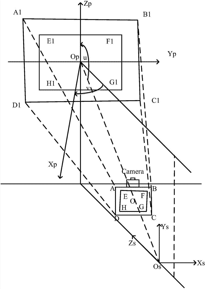
[0057] refer to figure 2 , is a schematic diagram of a projection system in this application. In the embodiment of the present application, the projector is usually placed under the screen and at a certain distance from the wall. Of course, the present application is also applicable to other projector placement methods.

[0058] On the screen, take the point Op where the light source Os of the projector reaches the wall through the center of the lens as the coordinate origin, and establish a screen coordinate system OpXpYpZp. The Xp axis is the direction perpendicular to the wall, the Yp axis is the horizontal direction, and the Zp axis is the vertical direction. .

[0059] Inside the projector, the ...


PUM


Abstract

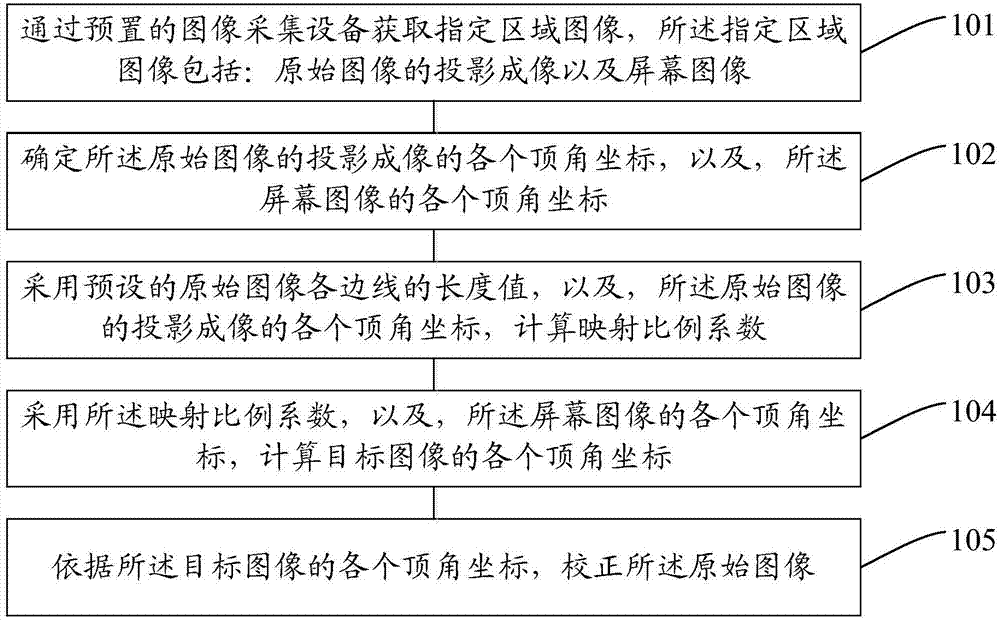
The embodiment of the application provides an automatic projection imaging correction method. The method comprises the following steps: obtaining a specified area image via a preset image collection device, wherein the specified area image comprises a projection mage of an original image and a screen image; determining vertex angle coordinates of the projection mage of the original image, and thevertex angle coordinates of the screen image; calculating a mapping proportion coefficient by using preset length values of side lines of the original image and the vertex angle coordinates of the projection mage of the original image; calculating the vertex angle coordinates of a target image by using the mapping proportion coefficient and the vertex angle coordinates of the screen image; and correcting the original image by using the vertex angle coordinates of the target image. According to the embodiment of the invention, no user operation is needed, so that the laser TV can be debugged without a professional debugger.

Description

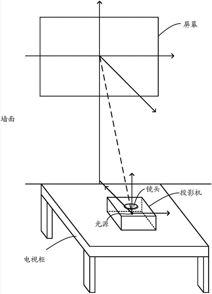
technical field [0001] The present application relates to the technical field of image processing, in particular to an automatic calibration method for projection imaging, an automatic calibration device for projection imaging, and a laser television. Background technique [0002] Laser TV is a new product that combines laser light source with ultra-short-throw projector technology. refer to figure 1 A schematic diagram of a laser TV. Laser TV includes: projector, TV cabinet, screen. The projector can project vertically upwards. When placed on the TV cabinet close to the wall, it can project large-scale projection images to the screen. In order to perfectly display the image, the parallel relationship between the projection plane of the screen and the lens of the projector is very strict. [0003] When installing a laser TV, professionals are required to correct the position of the projector body, and then fix the projector body to the TV cabinet with screws so that the p...

Claims


Application Information

Patent Timeline
Patent Type & Authority Applications(China)
IPC IPC(8): H04N9/31
Inventor 钟声
Owner 上海顺久电子科技有限公司
Learn More