
Floor beam structure applied to vehicle

A floor beam and floor technology, applied in the field of vehicles, can solve problems such as squeezed battery installation space, weak floor strength, battery fire, etc., to achieve the effects of improving battery life, dispersing impact force, and ensuring safety

Active Publication Date: 2018-01-09
GREAT WALL MOTOR CO LTD
View PDF6 Cites 7 Cited by
  • Summary
  • Abstract
  • Description
  • Claims
  • Application Information

AI Technical Summary

Problems solved by technology

[0002] Vehicles in related technologies, such as pure electric vehicles, have a relatively low floor structure, and the floor structure is similar to that of traditional vehicles with engines. There is not much space for battery layout, which affects the cruising range of the vehicle
At the same time, the batteries of general pure electric vehicles are arranged under the floor. When the vehicle collides, such as a frontal collision or a side collision, there are fewer force transmission channels, and the floor and the beams on the floor are seriously deformed, which excessively squeezes the battery installation space. Easy to detonate battery fire
In addition, the strength of the traditional floor is weak, and it cannot absorb the collision energy well during a collision, and there is no installation point for the functional modules and powertrain of the new energy vehicle in the cabin, which cannot meet the design requirements of the new energy vehicle

Method used


Image

  • Floor beam structure applied to vehicle
  • Floor beam structure applied to vehicle
  • Floor beam structure applied to vehicle

Examples


Embodiment Construction

[0055] It should be noted that, in the case of no conflict, the embodiments of the present invention and the features in the embodiments can be combined with each other.

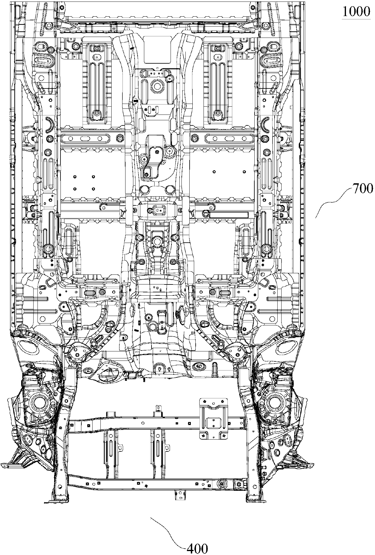
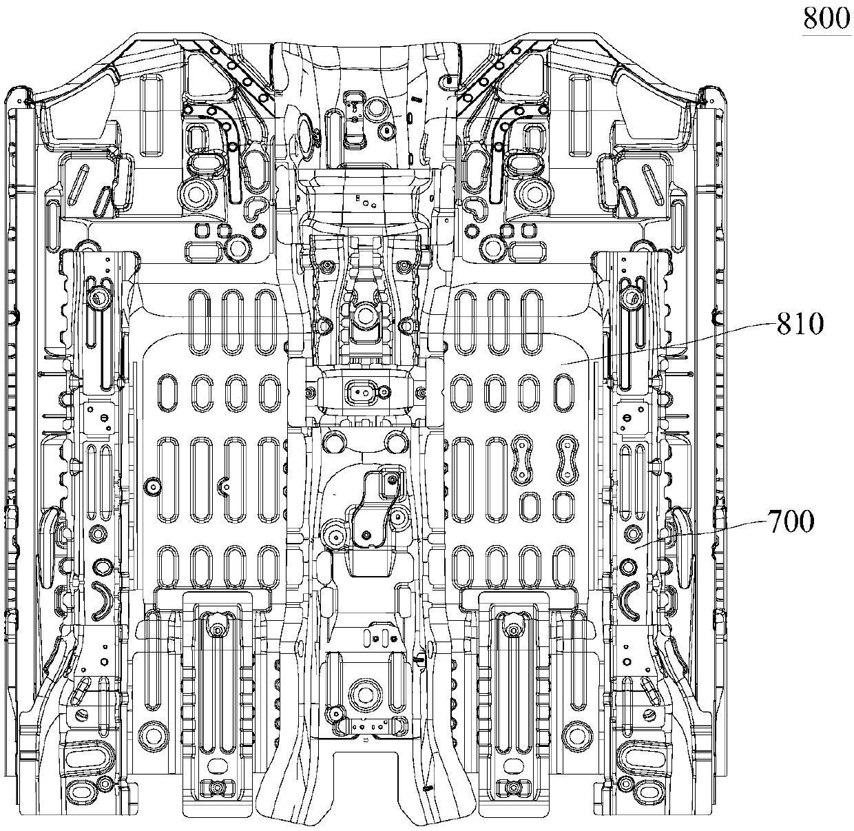
[0056] Combine below Figure 1 to Figure 23The floor assembly 1000 for a vehicle according to the embodiment of the present invention will be described in detail.

[0057] Such as Figure 1 to Figure 3 As shown, the floor assembly 1000 for a vehicle according to the embodiment of the present invention may include a power assembly 900 and a floor assembly 800 , wherein the power assembly 900 further includes a cabin installation frame structure 400 and a plurality of functional modules.

[0058] Such as Figure 9-Figure 12 As shown, the cabin installation frame structure 400 includes a crossbeam 410 and a plurality of connecting longitudinal beams 420, the crossbeam 410 includes a front crossbeam 411 and a longitudinal crossbeam 410, the front crossbeam 411 and the rear crossbeam 412 are spaced apart from f...


PUM


Abstract

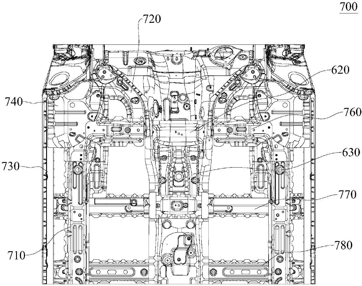
The invention provides a floor beam structure applied to a vehicle. The structure comprises a middle channel, underfloor longitudinal beams, floor cross beams and inclined connecting beams, wherein the underfloor longitudinal beams are located on the left side and the right side of the middle channel; the floor cross beams are disposed on the left side and the right side of the middle channel, thefloor cross beam on each side is connected to the underfloor longitudinal beam on the same side and the middle channel; and the inclined connecting beams are connected to the left side and the rightside of the middle channel, and the front end of the inclined connecting beam on each side is connected to the underfloor longitudinal beam on the same side, and the rear end is connected to the floorcross beam on the same side and the middle channel. The floor beam structure applied to the vehicle provided by the invention has more force transmission channels, so serious deformation of a floor generated when the vehicle suffers impact can be avoided.

Description

technical field [0001] The invention relates to the technical field of vehicles, in particular to a floor beam structure for vehicles. Background technique [0002] Vehicles in related technologies, such as pure electric vehicles, have a relatively low floor structure, and the floor structure is similar to that of traditional vehicles with engines. There is not much space for battery layout, which affects the cruising range of the vehicle. At the same time, the batteries of general pure electric vehicles are arranged under the floor. When the vehicle collides, such as a frontal collision or a side collision, there are fewer force transmission channels, and the floor and the beams on the floor are seriously deformed, which excessively squeezes the battery installation space. It is easy to detonate the battery and cause a fire. In addition, the strength of the traditional floor is weak, and it cannot absorb the collision energy well during a collision, and there is no install...

Claims


Application Information

Patent Timeline
Patent Type & Authority Applications(China)
IPC IPC(8): B62D25/20
Inventor 杨鸿展蒋晨龙罗泽王杰马红阳赵旭亮朱学文
Owner GREAT WALL MOTOR CO LTD
Learn More