

Method capable of reducing yield of slurry oil of catalytic cracking device
A catalytic cracking device and catalytic cracking raw material technology, applied in the direction of catalytic cracking, cracking, petroleum industry, etc., can solve the problems of reducing oil slurry yield, difficult to form emulsified state, unfavorable production, etc., to improve dispersion and atomization degree, improve the distribution of cracked products, and reduce the effect of slurry yield
Inactive Publication Date: 2018-01-09
CHINA PETROLEUM & CHEM CORP
View PDF4 Cites 0 Cited by
- Summary
- Abstract
- Description
- Claims
- Application Information
AI Technical Summary
Problems solved by technology
[0005] However, none of the prior art mentions that the oil slurry yield can be reduced, and all of them emulsify catalytic cracking raw materials at normal pressure and lower temperature (below 100°C). In the industrial production process, the preheating temperature of catalytic cracking raw materials It is usually higher, reaching about 140°C t
Method used
View moreImage
Smart ImageViewing Examples

Examples
 PUM
 Abstract
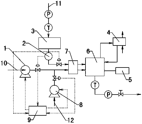
The invention provides a method capable of reducing the yield of slurry oil of a catalytic cracking device, belonging to the technical field of catalytic cracking of petroleum refining. The method ischaracterized in that a to-be-catalytically-cracked raw material, water and an emulsifier are mixed through a premixer, and then the obtained mixture enters an emulsifying device for emulsifying; themass ratio of the to-be-catalytically-cracked raw material to the water to the emulsifier is (92-94): (5.2-7): (0.8-1); emulsified oil obtained by emulsifying directly enters a catalytic device for acatalytic reaction; and the conditions of emulsifying in the emulsifying device are as follows: shearing and stirring are performed at a rotating speed of 6000 r/min to 8000 r/min, and a pressure of 1.0 MPa to 1.1 MPa and a temperature of 155 DEG C to 160 DEG C are maintained in the emulsifying device at the same time. The method provided by the invention improves the dispersity and the fogging degree of a catalytic cracking feeding material, improves the depth of cracking, and greatly reduces the yield of the slurry oil. Meanwhile, a calibration test is performed on an industrial device, so the distribution of a cracked product is improved, and the yield of the slurry oil is decreased by 1.51%.
Description
technical field [0001] A method for reducing the oil slurry yield of a catalytic cracking unit belongs to the technical field of catalytic cracking in petroleum refining. Background technique [0002] Existing methods to reduce the yield of catalytic cracking oil slurry are mainly achieved through new catalysts and catalytic cracking additives to reduce the yield of oil slurry. Catalysts and catalytic assistants mainly promote the deep conversion of heavy oil, increase the yield of light oil, and reduce the yield of oil slurry and coke by changing the catalytic reaction mechanism. These are mainly achieved by chemical methods to reduce the oil slurry yield, but the present invention proposes a method different from the prior art, that is, a physical method to reduce the catalytic cracking oil slurry yield. [0003] By changing the emulsified state of the raw material, the catalytic cracking raw material is dispersed finer and more uniform, sprayed into the riser reactor thr...
Claims
Login to View More Application Information
Patent Timeline
 IPC IPC(8): C10G11/00
Inventor许金山许晓斌周忠国达建文韩新竹刘爱华
OwnerCHINA PETROLEUM & CHEM CORP