Shutter type vacuum furnace inspection window

An observation window and vacuum furnace technology, applied in the field of flicker-free observation window structure and its protection, can solve the problems of observation window flicker, complex mechanism, high cost, etc., to avoid flicker, reduce the number of parts, and reduce the volume Effect

Inactive Publication Date: 2018-01-09
宁波鑫利成真空科技有限公司
View PDF7 Cites 3 Cited by
  • Summary
  • Abstract
  • Description
  • Claims
  • Application Information

AI Technical Summary

Problems solved by technology

[0007] Considering the current situation of the above-mentioned prior art, the technical problem to be solved by the present invention is to provide a flicker-free vacuum furnace observation mechanism based on the principle of pinhole imaging, which can completely overcome the existing "flicker window" structure in principle. The defects of the observation window flickering, complex mechanism, large volume and high cost greatly improve the performance of the observation window of the vacuum furnace

Method used


Image

  • Shutter type vacuum furnace inspection window

Examples


Embodiment Construction

[0017] In order to make the objectives, technical solutions and advantages of the present invention clearer, the present invention will be further described in detail below with reference to the accompanying drawings.

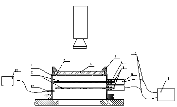
[0018] As shown in the figure, a shutter type vacuum furnace observation window includes an observation window cylinder 1 that can be installed in the observation port of the vacuum furnace, an imaging orifice 2 installed at the front end of the observation window cylinder 1, The rear end is provided with a glass lens 3 and a lens pressing plate 4 , and a sealing ring 5 for forming a vacuum sealing circuit between the lens 3 and the barrel 1 . An argon gas filling channel 6 is arranged between the glass lens 3 and the imaging aperture plate 2 . On the outer side of the glass lens 3 is an imaging lens barrel 7. A focusing lens 8 and an imaging lens 9 are arranged in the lens barrel 7 in turn. There is a circular hole with a diameter of 0.5-2 mm in the center of ...


PUM


Abstract

The invention relates to a shutter type vacuum furnace inspection window. The shutter type vacuum furnace inspection window comprises an inspection window cylinder which can be arranged on a vacuum furnace inspection opening, an imaging pore plate arranged at the foremost end of the inspection window cylinder, a glass optical lens, a lens pressing plate and a sealing ring which is arranged betweenthe lens and the cylinder and used for forming a vacuum sealing loop, wherein the glass optical lens and the lens pressing plate are arranged at the rear end of the inspection window cylinder. An argon inflating channel is formed between the glass optical lens and the imaging pore plate. An imaging lens cone is arranged on the outer side of the glass optical lens, and the lens cone is internallyprovided with a focusing lens and an imaging lens. Due to the fact that blade slits are driven to form a shutter through the rotation of the motor, the stroboflash phenomenon cannot be avoided. When an operator directly observes, visual fatigue can be caused by stroboflash, which is very harmful to the operator which works for a long time. When a camera is used for carrying out remote monitoring,due to the fact that the speed of the slit shutter is different from the scanning frequency of the camera, alternate dark space frequently appears on a remote monitoring screen. The problems are all caused by slit stroboflash and cannot be avoided.

Description

technical field [0001] The invention relates to a vacuum furnace observation window structure and a protection method, in particular to a stroboscopic-free observation window structure and a protection method thereof, which can work continuously for a long time and prevent volatile matter from adhering to the lens. Background technique [0002] During the smelting or evaporation process in the vacuum furnace, the staff often need to observe the materials and working conditions in the furnace, so as to grasp the situation in the furnace at any time, control and adjust the process and avoid accidents. This is particularly important for electron beam melting furnaces and vacuum coating equipment, but various evaporative substances in the furnace are often evaporated and attached to the lenses of the observation window, forming a shield and seriously hindering the operation of the staff. Therefore, a reliable and stable observation window that can protect the observation window ...

Claims


Application Information

Patent Timeline
Patent Type & Authority Applications(China)
IPC IPC(8): F27D21/02
Inventor 赵文天
Owner 宁波鑫利成真空科技有限公司
Why Eureka
Try Eureka