
A high power factor constant current control circuit and led lighting equipment

A constant current control circuit and high power factor technology, applied in lighting devices, energy-saving control technology, lamp circuit layout, etc., can solve problems such as damage to human eye health, LED load strobe, poor user experience, etc., to improve user experience performance, eliminate impact, eliminate the effect of stroboscopic phenomenon

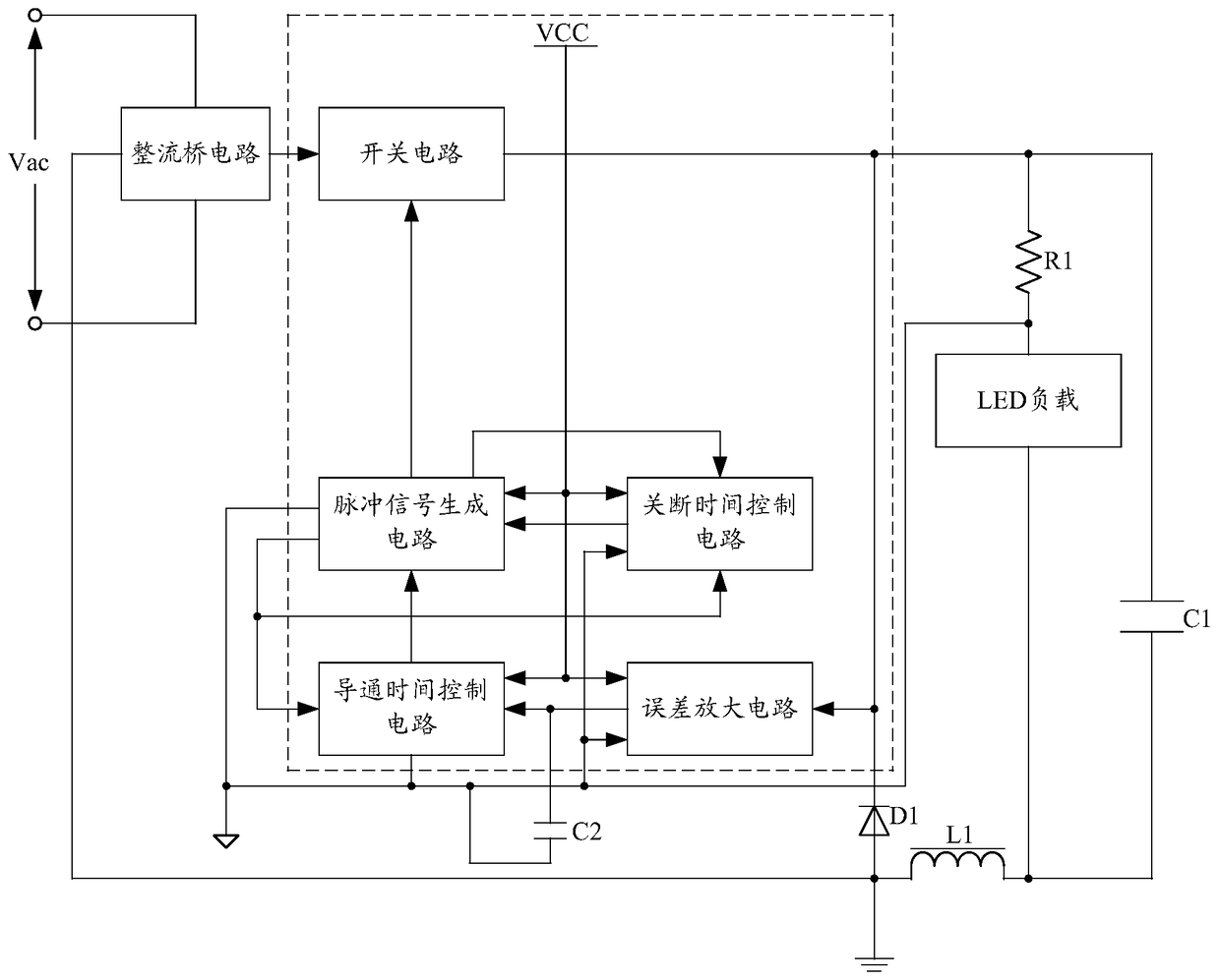
Active Publication Date: 2019-03-08
SHENZHEN SUNMOON MICROELECTRONICS
View PDF8 Cites 0 Cited by
  • Summary
  • Abstract
  • Description
  • Claims
  • Application Information

AI Technical Summary

Problems solved by technology

[0006] The purpose of the embodiment of the present invention is to provide a high power factor constant current control circuit, aiming to solve the problem that the existing high power factor constant current control circuit used to drive LED loads causes LED loads to flicker, which damages the health of human eyes and improves user experience. sex problem

Method used


Image

  • A high power factor constant current control circuit and led lighting equipment
  • A high power factor constant current control circuit and led lighting equipment
  • A high power factor constant current control circuit and led lighting equipment

Examples


Embodiment Construction

[0023] In order to make the object, technical solution and advantages of the present invention clearer, the present invention will be further described in detail below in conjunction with the accompanying drawings and embodiments. It should be understood that the specific embodiments described here are only used to explain the present invention, not to limit the present invention.

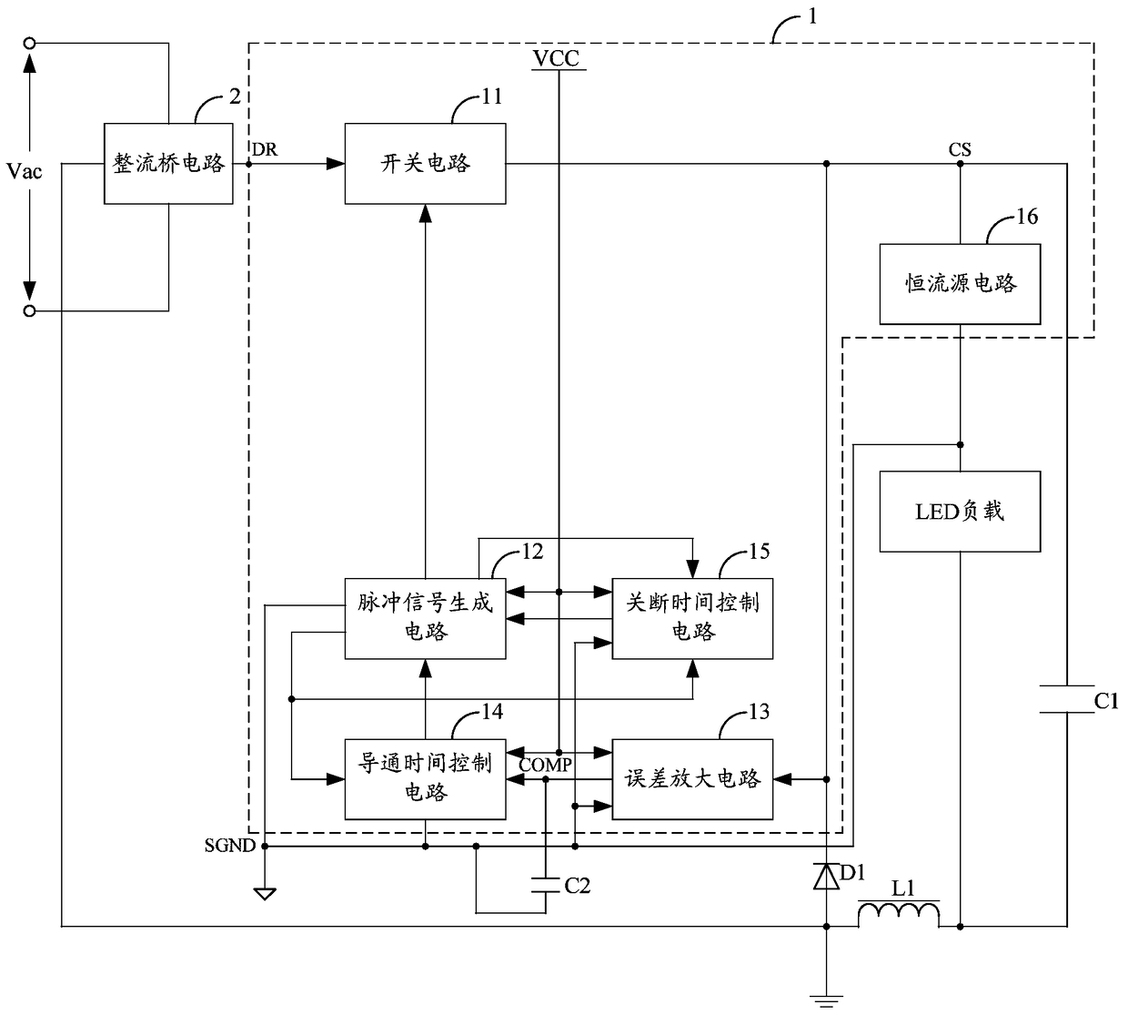
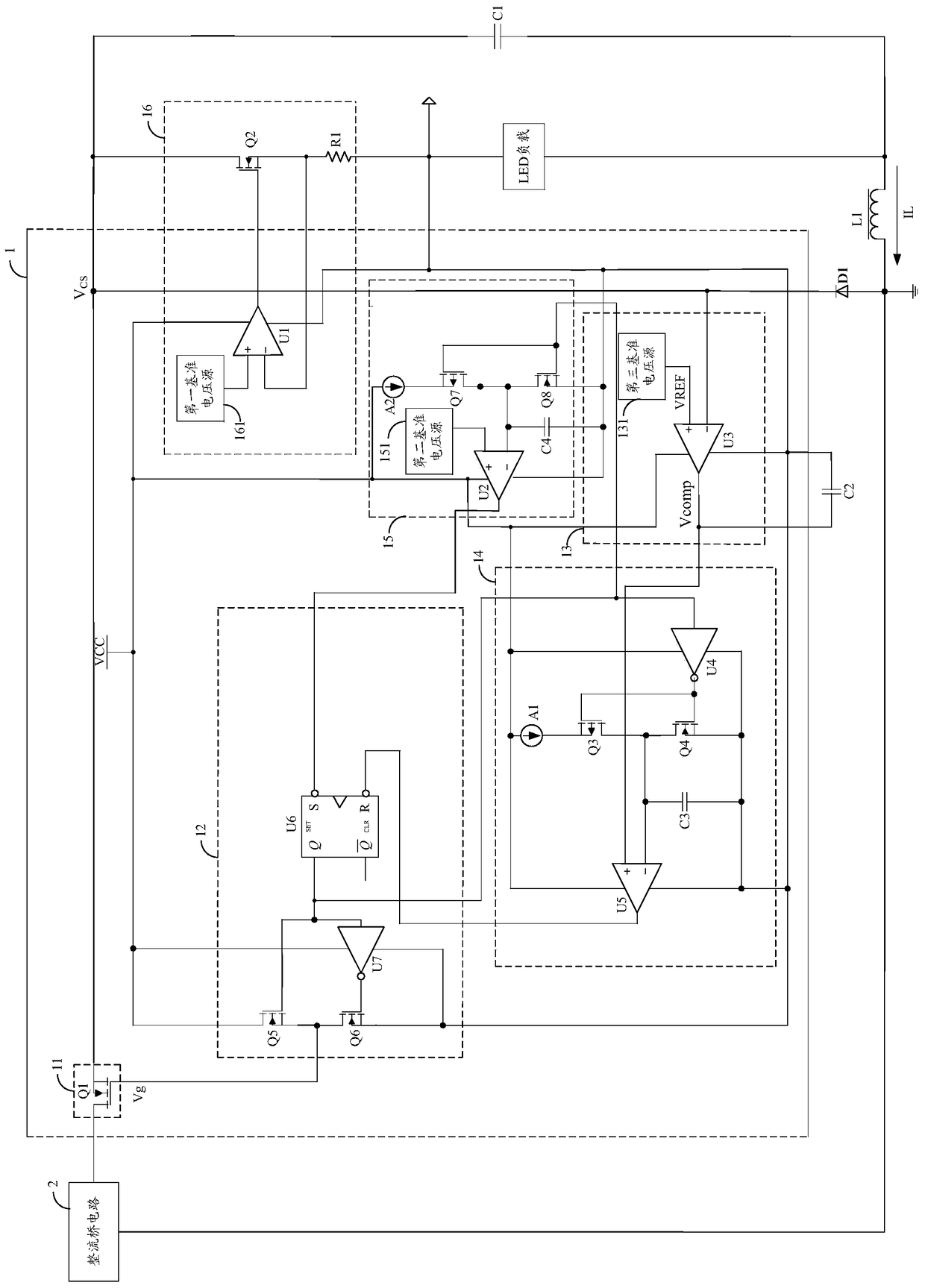
[0024] Aiming at the problems existing in the prior art, the present invention proposes a high power factor constant current control circuit, which is based on the existing high power factor constant current control circuit, adding a constant current source circuit to the constant current drive chip , the error amplifier circuit in the constant current drive chip samples the voltage of the first terminal (or input terminal) of the constant current source circuit, compares the sampled voltage with a reference voltage, and the two are amplified by error and output to the conductor The on-time control...


PUM


Abstract

The invention belongs to the technical field of LED (light emitting diode) illumination driving, and provides a high-power-factor constant-current control circuit and LED illuminating equipment. The high-power-factor constant-current control circuit is characterized in that a constant-current source circuit is arranged in a constant-current driving chip on the basis of the existing high-power-factor constant-current control circuit, an error amplifying circuit in the constant-current driving chip is used for sampling a voltage of a first end of the constant-current source circuit, the sampled voltage is compared to a reference voltage, the sampled voltage and the reference voltage are subjected to error amplification and then are outputted to a conduction time control circuit, the inputting voltage of the constant-current source circuit is adjusted by controlling make and break of a switch circuit, the constant-current source circuit can work in a normal constant-current state, constant current flows through an LED load, influences of ripple waves on the LED load are eliminated, strobing is eliminated, eyes of people can be protected, and user experiences are improved.

Description

technical field [0001] The invention belongs to the technical field of LED lighting driving, and in particular relates to a high power factor constant current control circuit and LED lighting equipment. Background technique [0002] Obtaining AC power from the grid and rectifying it to power load equipment is a common drive scheme. However, if the power factor of the load equipment connected to the AC grid is low, it will cause a certain degree of harmonic pollution to the public grid. [0003] In the field of LED lighting drive technology, in order to meet the requirements of high power factor while satisfying the constant current drive, the existing technology proposes a method of integrating active power factor correction and constant current in the constant current drive chip of the constant current control circuit. Output function to achieve high power factor constant current drive, such as figure 1 It shows the structure of the existing constant current control circu...

Claims


Application Information

Patent Timeline
Patent Type & Authority Patents(China)
IPC IPC(8): H05B37/02
CPCY02B20/40
Inventor 林道明付凌云于井亮李照华赵春波朱兴安
Owner SHENZHEN SUNMOON MICROELECTRONICS
Learn More