
Double-taper sleeve type self-lubricating spherical plain bearing pad friction and wear test device

A friction and wear test, joint bearing technology, applied in the direction of measuring devices, wear resistance testing, instruments, etc., can solve the problems of different deformation, can not reflect the actual contact of the bearing liner, etc., to facilitate disassembly, solve the test analysis Convenience, accuracy and reliability of test conditions, and the effect of solving device requirements for accurate measurement and analysis

Active Publication Date: 2019-07-26
YANSHAN UNIV
View PDF9 Cites 0 Cited by
  • Summary
  • Abstract
  • Description
  • Claims
  • Application Information

AI Technical Summary

Problems solved by technology

At the same time, under the action of loading force, the deformation of the two separated semi-annular surfaces and the entire toroidal surface of the inner ring of the joint bearing is not the same, and the two semi-annular surfaces cannot be concentric and coaxial like the entire toroidal surface
[0004] Therefore, the existing two performance test methods cannot not only reflect the actual contact of the bearing liner, but also facilitate the measurement and analysis of the friction surface performance after the test.

Method used


Image

  • Double-taper sleeve type self-lubricating spherical plain bearing pad friction and wear test device
  • Double-taper sleeve type self-lubricating spherical plain bearing pad friction and wear test device
  • Double-taper sleeve type self-lubricating spherical plain bearing pad friction and wear test device

Examples


Embodiment Construction

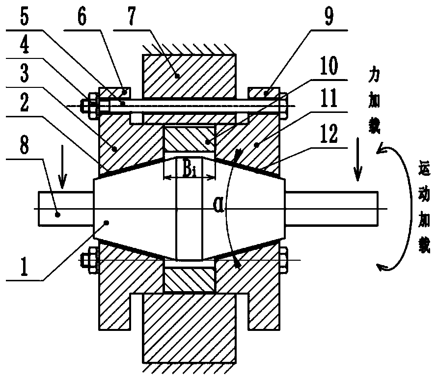
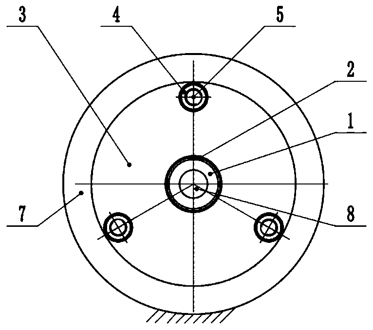
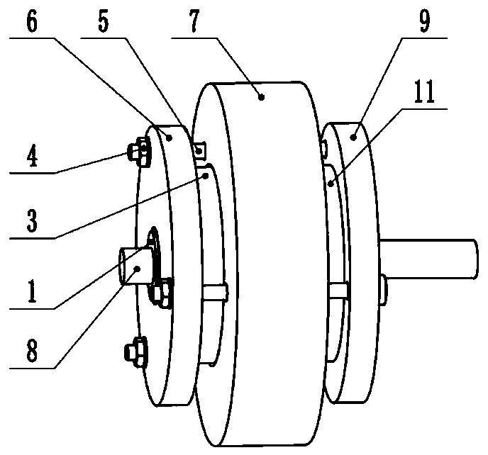
[0016] exist figure 1 , figure 2 and image 3 In the schematic diagram of the friction and wear test device for the double-cone bushing type self-lubricating joint bearing liner shown, the main body of the double-cone shaft 1 is composed of two identical truncated cones with large diameter ends respectively connected to the two ends of the same cylinder , the cone angle of the two truncated cones is α, and α=25°. Short shafts 8 coaxial with the small diameter ends of the two truncated cones are all provided. On the two cones of the double cone shaft, there are corresponding taper sleeves, that is, the left taper sleeve 3 and the right side taper sleeve 11. The central through hole of the cylindrical base of the two taper sleeves is the truncation of the double taper shaft. The conical through hole corresponding to the cone has a cone angle of α. A left flange 6 and a right flange 9 are connected to the small central hole of the cylindrical substrate and have the same end ...


PUM


Abstract

The invention relates to a friction-wear test device for a double cone shaft sleeve type self-lubricating joint bearing bush. Taper corresponding sleeves separately sleeve the two cone bodies of a double cone shaft; a flange which is integrally connected with the taper sleeve and shares the same end surface is arranged on each of the taper sleeves; 3-8 through holes are uniformly distributed in each of the flanges; the inner end surfaces of the two cone shafts are in separate contact with the two end surfaces of a precise isolating sleeve; the inner diameter of the precise isolating sleeve sleeving outer side of the middle of the double cone shaft is greater than the diameter of a cylinder portion of the double cone shaft, and the outer diameter is smaller than or equal to that of a cylindrical base body of each of the taper sleeves; concentric locating sleeves are arranged on the outer peripheral surfaces of the precise isolating sleeve and taper sleeves on two sides; an axial throughhole which corresponds to the through hole of the flange of each of the taper holes and is coaxial to the same is formed in a ring-shaped body of each of the concentric locating sleeves; and a screwpenetrating through each of the through holes of the concentric locating sleeves also penetrates through the through hole on the flanges of the two cone sleeves and is fastened by a nut. The device provided by the invention not only can simulate the actual bush working condition in a bearing well, but also can change the initial working condition conveniently. After the test, the device is conveniently detached and analyzed, and can support precise detection of the test.

Description

technical field [0001] The invention relates to a test device for a joint bearing, in particular to a test device for detecting the friction and wear performance of a self-lubricating liner of a joint bearing under the working condition of the bearing. Background technique [0002] Self-lubricating spherical plain bearing is a kind of spherical sliding bearing. Because of its simple and compact structure, large load capacity, maintenance-free, and its sliding friction surface is spherical, it can be applied to flexible swing connections within a certain angle range, and is widely used in aerospace. And military equipment and other high-precision equipment. A self-lubricating liner layer is pasted between the inner ring and the outer ring of the self-lubricating joint bearing. The mechanical properties of the liner, such as the friction and wear performance of the liner, the adhesion performance of the liner and the inner surface of the outer ring, The no-load starting frict...

Claims


Application Information

Patent Timeline
Patent Type & Authority Patents(China)
IPC IPC(8): G01N3/02G01N3/56
Inventor 陈继刚姚冀川付敬文郭稣民李祥瑞
Owner YANSHAN UNIV
Learn More