
Liquid crystal lens, manufacturing method of liquid crystal lens and display device

A technology of liquid crystal lens and manufacturing method, which is applied in optics, instruments, nonlinear optics, etc., can solve the problems of abnormal shape, light crosstalk, and high refractive index in the edge area of ​​liquid crystal repeating unit, so as to improve the vertical state and improve the crosstalk phenomenon , Improve the effect of the display effect

Inactive Publication Date: 2018-01-09
BOE TECH GRP CO LTD
View PDF4 Cites 0 Cited by
  • Summary
  • Abstract
  • Description
  • Claims
  • Application Information

AI Technical Summary

Problems solved by technology

However, since there is also an electric field between the strip electrode and the upper electrode that is not directly facing itself, the direction of the electric field force in the electric field is not perpendicular to the lower substrate, so the vertical state of the liquid crystal molecules in the edge region of the liquid crystal repeating unit cannot be abruptly changed. Cause abnormal morphology here (such as image 3 , Figure 4 The simulation results shown above), lead to a higher refractive index in the edge region of the liquid crystal repeating unit, which in turn causes disordered light when the light passes through the edge of the liquid crystal repeating unit, and light crosstalk occurs, which ultimately affects the display effect of the 3D display device.

Method used


Image

  • Liquid crystal lens, manufacturing method of liquid crystal lens and display device
  • Liquid crystal lens, manufacturing method of liquid crystal lens and display device
  • Liquid crystal lens, manufacturing method of liquid crystal lens and display device

Examples


Embodiment Construction

[0043] Example embodiments will now be described more fully with reference to the accompanying drawings. Example embodiments may, however, be embodied in many forms and should not be construed as limited to the examples set forth herein; rather, these embodiments are provided so that this disclosure will be thorough and complete and will fully convey the concept of example embodiments to those skilled in the art. The described features, structures, or characteristics may be combined in any suitable manner in one or more embodiments. In the following description, numerous specific details are provided in order to give a thorough understanding of embodiments of the present disclosure. However, those skilled in the art will appreciate that the technical solutions of the present disclosure may be practiced without one or more of the specific details being omitted, or other methods, components, devices, steps, etc. may be adopted. In other instances, well-known technical solution...


PUM

PropertyMeasurementUnit
widthaaaaaaaaaa
widthaaaaaaaaaa

Abstract

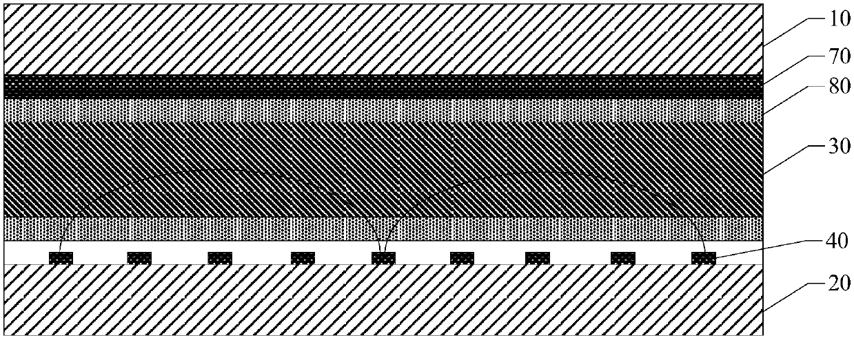
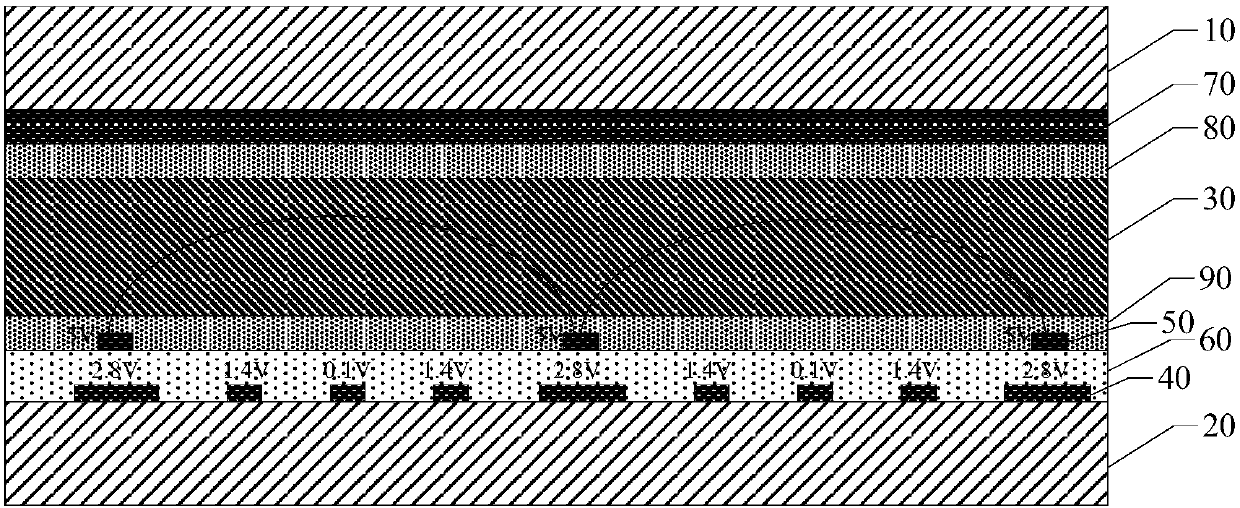
The invention relates to a liquid crystal lens, a manufacturing method of the liquid crystal lens and a display device and relates to the technical field of display. The liquid crystal lens comprisesan upper substrate, a lower substrate, a liquid crystal layer arranged between the upper substrate and the lower substrate and including multiple liquid crystal repetition units, a first electrode layer arranged on the lower substrate and including strip-shaped electrode groups corresponding to the liquid crystal repetition units, a second electrode layer superposed on the first electrode layer and including multiple third strip-shaped electrodes, wherein the upper substrate and the lower substrate are oppositely arranged, each strip-shaped electrode group includes two first strip-shaped electrodes and a second strip-shaped electrode located between the first strip-shaped electrodes, the third strip-shaped electrodes correspond to the first strip-shaped electrodes in a one-to-one mode. Theliquid crystal lens can improve the phenomenon of crosstalk of the adjacent liquid crystal units and thus improve a display effect.

Description

technical field [0001] The present disclosure relates to the field of display technology, and in particular to a liquid crystal lens, a method for manufacturing the liquid crystal lens, and a display device. Background technique [0002] In the field of display technology, 3D display is usually realized by simulating the slightly different pictures observed by the human eyes when observing a three-dimensional object. To achieve the purpose of 3D display, a liquid crystal lens is usually arranged in a liquid crystal display device. The liquid crystal lens includes a plurality of liquid crystal repeating units, and each liquid crystal repeating unit is equivalent to a columnar lens. When the light presenting the same picture passes through the liquid crystal lens, each liquid crystal repeating unit focuses the light in different directions, so that the entering The light is different for the user's left and right eyes. [0003] For example, a liquid crystal lens may include a...

Claims


Application Information

Patent Timeline
Patent Type & Authority Applications(China)
IPC IPC(8): G02F1/1343G02F1/1333G02F1/1337G02B27/22
Inventor 王海燕
Owner BOE TECH GRP CO LTD
Learn More