A method for manufacturing an integrated three-dimensional LED display module

A technology of three-dimensional display and manufacturing method, which is applied in the direction of identification devices, instruments, optics, etc., can solve problems such as complex process, crosstalk of polarized light, and influence on 3D display effect, and achieve the effect of simple process and smooth surface

Active Publication Date: 2019-06-14
CHANGCHUN CEDAR ELECTRONICS TECH CO LTD
View PDF8 Cites 0 Cited by
  • Summary
  • Abstract
  • Description
  • Claims
  • Application Information

AI Technical Summary

Problems solved by technology

In the first method, when potting glue, the potting glue at the edge is easy to flow downward, which affects the splicing between modules, and the process is complicated, the curing time is long, and it is not easy to realize; the polarizing strip is not easy to stick flat
The second method is that when the ambient temperature is high, the edge is easy to warp due to the failure of the 3M transparent double-sided adhesive
Both of the above two production methods have the problem of positioning the pixels of the lower module when pasting the polarizing strip, and the phenomenon of crosstalk between left and right circularly polarized light, which affects the 3D display effect

Method used


Image

  • A method for manufacturing an integrated three-dimensional LED display module
  • A method for manufacturing an integrated three-dimensional LED display module
  • A method for manufacturing an integrated three-dimensional LED display module

Examples


Embodiment 1

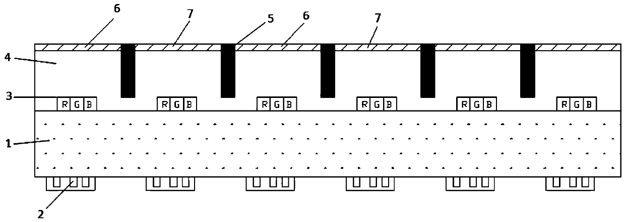
[0035] like figure 1 As shown, the integrated package LED display module includes a driver IC2, a driver circuit board 1, an LED lamp module 3, and an encapsulation glue 4. The driver IC2 is welded on the back of the driver circuit board 1, and the LED lamp module 3 is fixed on the driver circuit board 1. On the front side, the size of the blue and green LED chips is: 7mils*9mils, and the size of the red LED chips is 6mils*6mils. The thickness of the encapsulant 4 is not specifically limited. Encapsulation glue 4 adopts epoxy resin AB glue, and the ratio of component A to component B is 2:1. A scattering agent is added to the packaging glue 4, wherein the proportion of the scattering agent is 5.3%-10.6% of the total mass of the epoxy resin AB glue.

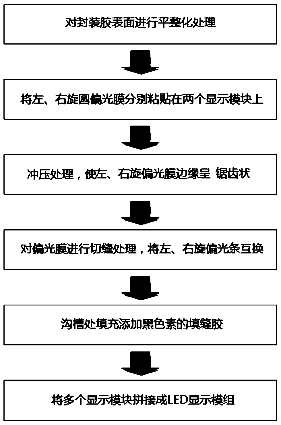
[0036] like figure 2 As shown, the manufacturing method of the LED display module is as follows:

[0037] Step 1: Use the method of fine milling or grinding to process the surface flatness of the packaging glue 4 of the displ...

Embodiment 2

[0048] like figure 1 As shown, the integrated package LED display module includes a driver IC2, a driver circuit board 1, an LED lamp module 3, and an encapsulation glue 4. The driver IC2 is welded on the back of the driver circuit board 1, and the LED lamp module 3 is fixed on the driver circuit board 1. On the front side, the size of the blue and green LED chips is: 7mils*9mils, and the size of the red LED chips is 6mils*6mils. The thickness of the encapsulant 4 is not specifically limited. Encapsulation glue 4 adopts epoxy resin AB glue, and the ratio of component A to component B is 2:1. A scattering agent is added to the packaging glue 4, wherein the proportion of the scattering agent is 5.3%-10.6% of the total mass of the epoxy resin AB glue.

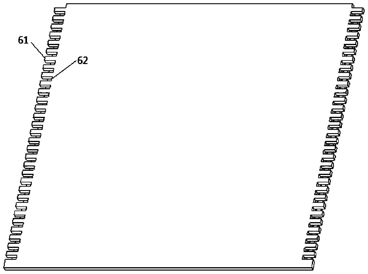
[0049] like Image 6 As shown, the manufacturing method of the LED display module is as follows:

[0050] Step 1: Use fine milling or grinding to process the surface flatness of the packaging glue 4 of the display module, so t...


PUM


Abstract

The invention relates to a manufacture method for integrated-type three-dimensional LED display module group. A first technical scheme of the method includes adhering a levo circular polarization film and a dextro circular polarization film onto surfaces of two display modules respectively, and punching the films to enable edges of the levo circular polarization film and the dextro circular polarization film to be sawtoothed; slotting the levo circular polarization film and the dextro circular polarization film into levo and dextro circular polarization strips; exchanging the circular polarization strips on the two display modules by a film rotation tool in an line or row spacing mode; splicing the display modules into the display module group. A second technical scheme of the method includes slotting the display modules; adhering the levo circular polarization film and the dextro circular polarization film to the display modules alternately by taking slots as barriers; filling the slots with seam sealants; finally, splicing the display modules into the display module group. The manufacture method has the advantages that process is simple, surface is smooth, edge upwarp caused by environment factor change is avoided, accurate positioning between the polarization strips and pixel points is realized, and interference between levo circular polarized light and dextro circular polarized light can be improved.

Description

technical field [0001] The invention belongs to the technical field of three-dimensional LED flat panel display, and relates to a manufacturing method of a three-dimensional LED display module. Background technique [0002] The current relatively mature commercial stereoscopic display methods usually adopt two forms: electronic shutter type and polarized projection type. Electronic shutter type 3D display requires observers to wear electronic shutter type stereoscopic glasses. This solution not only has high viewing costs when the number of viewers is large, but also causes visual fatigue and dizziness due to the rapid switching of images between the left and right eyes. For polarized projection 3D display, a left-handed and a right-handed circular polarizing film are respectively installed in front of the two projectors, and the images are fused and modulated to form a polarized 3D display system. The audience wears polarized glasses, and the left and right eye positions o...

Claims


Application Information

Patent Timeline
Patent Type & Authority Patents(China)
IPC IPC(8): G09F9/33G02B27/26G02B30/25
CPCG02B30/25G09F9/33
Inventor 马新峰孙天鹏肖传武赵文龙韩悦王聪
Owner CHANGCHUN CEDAR ELECTRONICS TECH CO LTD
Why Eureka
Try Eureka