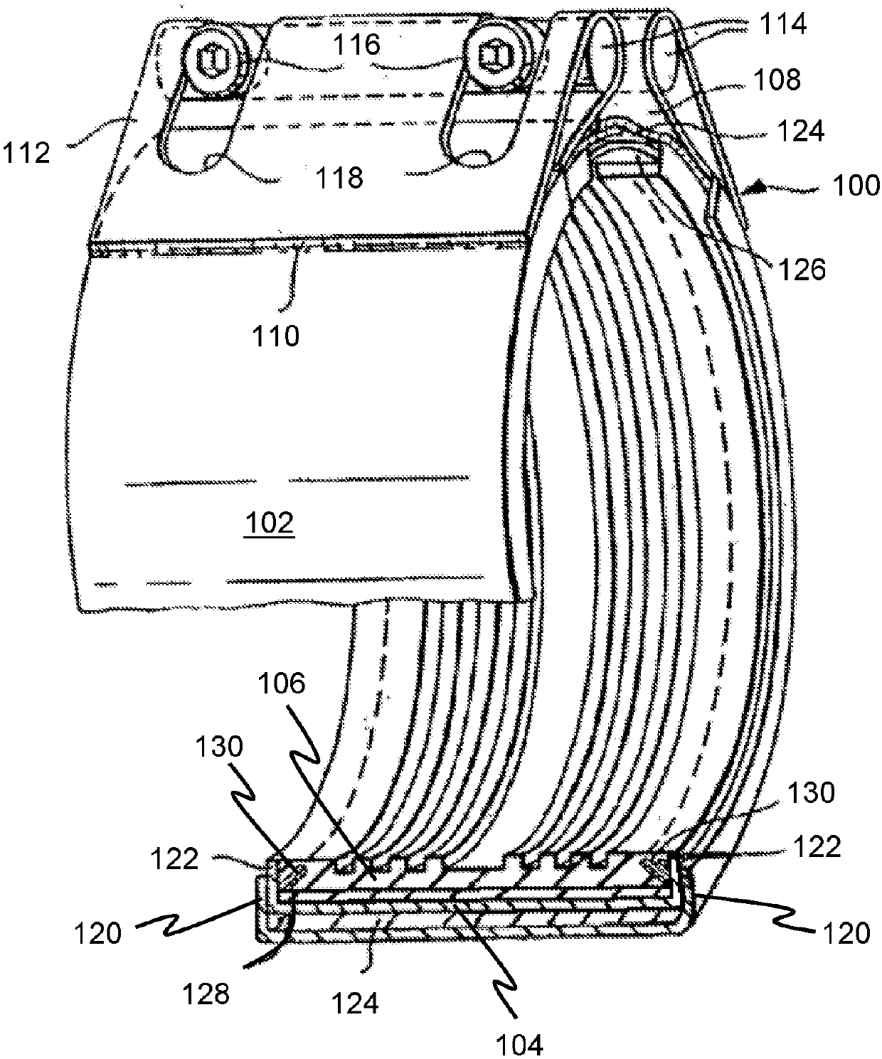
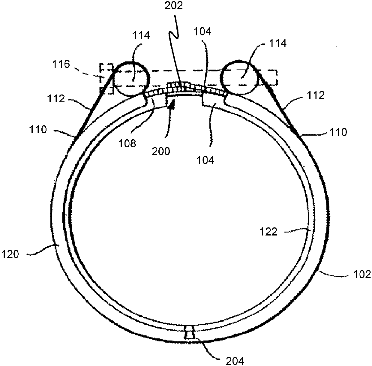
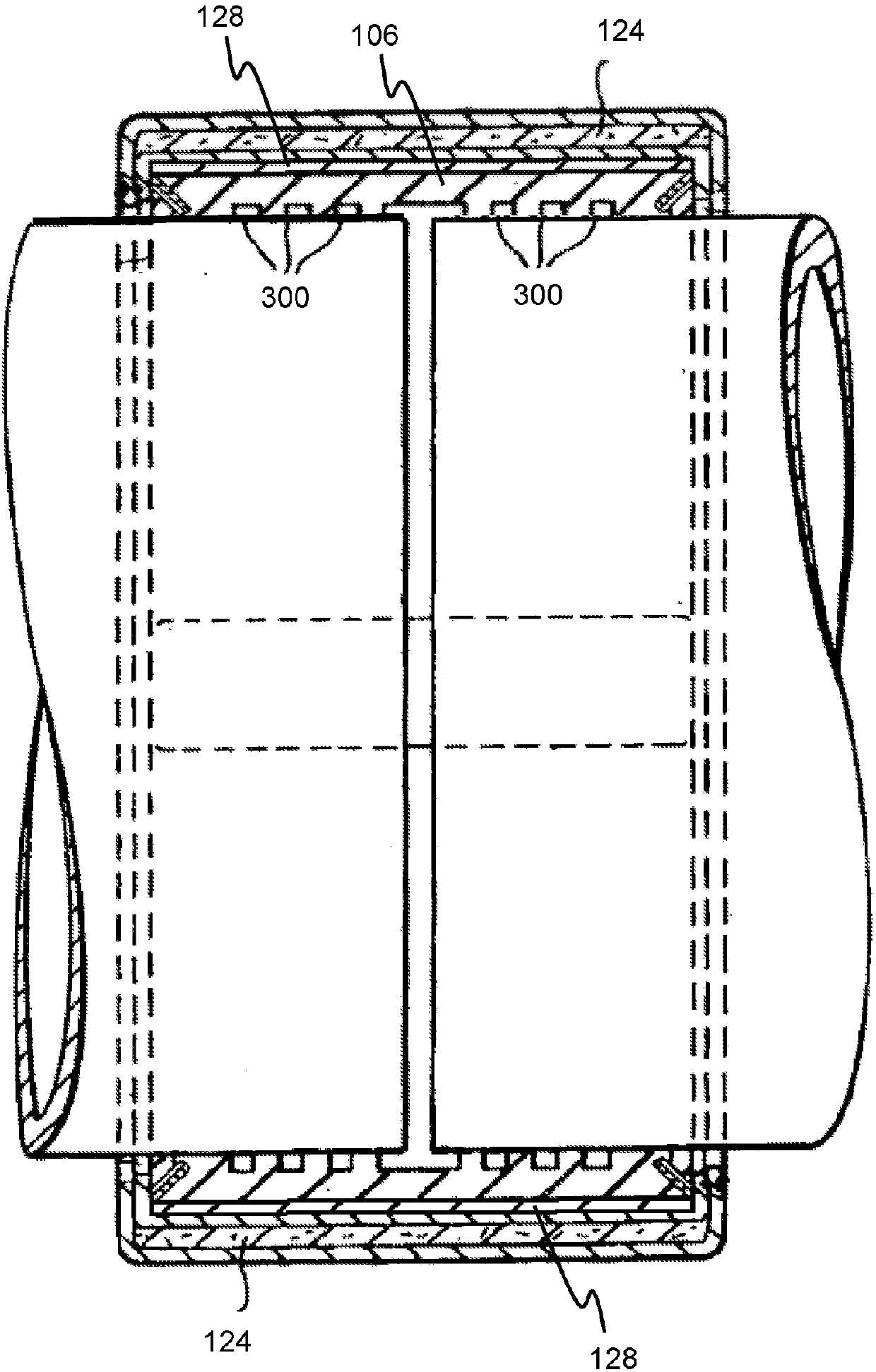
[0059] The pipe coupling 100 includes a tubular outer casing 102, a tubular inner casing 104 and a tubular sealing gasket 106. The tubular outer casing 102 is formed of rolled steel and has a longitudinal gap 108. The shell is folded back on itself at its free end and welded at 110 to form a loop 112 along the opposite edge of the longitudinal gap 108. A pin 114 is inserted in the ring. The tension screw 116 passes through a transverse hole in one of the pins 114 into a threaded transverse hole in the other pin of the pins 114 to connect the two free ends of the outer shell 102 to each other.
[0060] A slot 118 is cut in the ring 112 to provide space for the screw. The axial end edge of the housing 102 is bent inwardly at a right angle to form an annular flange 120.
[0061] The tubular inner casing 104 is formed of rolled steel and has a longitudinal gap. The axial end edge of the inner housing 104 is bent inwardly at a right angle to form an annular flange 122. The inner shell 104 is fitted inside the outer shell 102, and the axial length of the inner shell 104 is slightly smaller than the axial length of the outer shell 102 so that the flange 122 is fitted inside the flange 120.
[0062] The gasket is an elastomer material, such as rubber or synthetic rubber.
[0063] The outer casing 102 is formed to have an inner diameter larger than the outer diameter of the inner casing 104 so as to accommodate the refractory material layer 124. The refractory material layer is a treated material strip, and considering the overlap and tolerance, the treated material strip is cut into the outer circumference of the inner shell +1%. The refractory layer may include two or more material layers. In a preferred example, the refractory layer includes two material layers, and the thickness of each layer is about 1.0 mm. The outer steel shell 102 and the inner steel shell 104 are separated from each other by a refractory material layer 124.
[0064] The outer casing 102 and the inner casing 104 are shaped to be smooth and identical, so that when the coupling is closed, a refractory material is provided with a low friction surface for easy sliding.
[0065] This is important because a coupling with only one housing does not provide a low friction surface between the steel housing and the rubber gasket or sealing sleeve.
[0066] The longitudinal gap of the outer casing 102 and the longitudinal gap of the inner casing 104 are aligned, and a bridging member 126 is provided to complete the circumferential band. This is to control the smooth sliding of the refractory layer 124 when the coupling is closed. The bridge member 126 is fixed to the inner side portion of the inner housing 104 by spot welding.
[0067] The bridging member 126 subtends an angle between about 30 degrees and about 40 degrees at the tube axis. The bridging member 126 is fixed to the inner casing 104 only on one side of the longitudinal gap, and the bridging member 126 is arranged to overlap the inner casing by approximately equal amounts on both sides of the gap when in the tensioned position.
[0068] In addition to the refractory layer 124, the coupling 100 also includes a layer 128 of insulating material. The inner housing 102 is formed to have an inner diameter larger than the outer diameter of the gasket 106 so as to accommodate the insulating material layer 128. The heat-insulating material layer is a treated material strip, and considering the overlap and tolerance, the treated material strip is cut into the outer circumference of the gasket +1%. The thermal insulation layer may include two or more material layers. In a preferred example, the thermal insulation layer includes two material layers, each of which has a thickness of about 0.5 mm. The inner steel shell 104 and the gasket 106 are separated from each other by an insulating material 128.
[0069] The coupling also includes a pair of frusto-conical clamping rings 130. Each ring 130 is provided in a corresponding groove formed in the outer surface of the gasket at each axial end. The outer end of each groove is located at the axial end of the outer surface. The slope of the groove makes the inner end closer to the axial center of the gasket than the outer end.
[0070] Each ring 130 is formed by a pair of arc-shaped sections and includes a set of hard teeth to pierce the gasket 106 at the bottom of the groove and bite into the surface of the tube, thereby providing the coupling to lock the tube against axial movement . The teeth are designed such that, for each tooth, the teeth are in contact around the circumference with a width of approximately 2 mm at a central portion of approximately 5 mm, thereby forming approximately 40% contact around the tube.
[0071] Refer now figure 2 , The longitudinal gap 200 in the inner shell 104 and the overlapping portion 202 of the refractory layer 124 can be seen.
[0072] In order to prevent the two shells from rotating relative to each other, an anti-rotation notch 204 is provided in the end flange 120 of the outer shell and the end flange 122 of the inner shell. The anti-rotation notch 204 is in contact with the gaps 108 and 200. Engage each other at diametrically opposite points to lock the two housings together. It is important that the two housings do not rotate relative to each other.
[0073] The sealing gasket 106 includes a series of ribs 300 to achieve effective sealing at a high hydrostatic pressure of, for example, 32 bar or even 64 bar. However, the axial length of the gasket exposed to hydrostatic pressure is smaller than the total axial length of the coupling.
[0074] The refractory layer 124 is made of an inorganic material, preferably mainly formed of silica. The material is formed of woven silica fibers and can be impregnated with vermiculite. In addition, the material can be coated with high temperature resistant polyurethane to reduce the possibility of wear of the woven material and restrict water from entering the coupling.
[0075] The refractory material is formed as a rectangular band wrapped around the inner casing. The end of the belt forms an overlap 202 in the area of the gaps 108 and 200.
[0076] The heat insulation layer 128 is made of mica. The material of this example is formed of mica paper and is particularly preferred. Mica paper includes phlogopite and bonding materials. Mica paper contains about 10% of the bonding material, and the bonding material is silicone resin. In this example, the density of mica paper is about 2.1kg/m 3.
[0077] During assembly, a complete one-piece inner shell including a heat insulation layer and a gasket is placed inside the outer shell, and a refractory layer is inserted between the outer shell and the inner shell to isolate the outer shell and the inner shell. Therefore, it can be seen that the outer shell 102 and the inner shell 104 are isolated by the refractory layer 124, and the gasket 106 and the inner shell 104 are thermally isolated by the heat insulation layer 128.
[0078] Figure 4 show Figure 1 to Figure 3 An improved example of the pipe coupling. The pipe coupling 100 is shown as being arranged on the pipe 400 in a pre-tensioned manner. The gasket 106 including the rib 300 is shown as further including an extension 402 located between the end surface of the annular flange 122 and the outer surface of the tube 400 to form an end seal. Therefore, liquid and dirt are prevented from entering the coupling from the outside.
[0079] In this example, the width of the inner housing 104 is smaller than the inner width of the outer housing 102 between the flanges 120. versus Figure 1 to Figure 3 Compared with the example of, the reduction in the width of the inner shell 102 is to accommodate the skirt 404 of the refractory layer 124. The skirt portion extends between the outer shell 102 and the inner shell 104. The skirt has a length sufficient to reach at least the outer surface of the tube 400. In other examples (not shown), the skirt may have a length extending away from the coupling and along a portion of the outer surface of the tube 400.
[0080] By providing the skirt, the outer end surface of the coupling-the outer end including a part of the gasket and a part of the annular flange 122-is further protected against flames.
[0081] Figure 4 The coupling is the same as the coupling described above in all other respects.