
Telescopic motor rotor winding device

A technology of motor rotor and winding device, applied in electromechanical devices, manufacturing motor generators, electrical components, etc., can solve problems such as affecting product quality, winding separation, decoupling, etc.

Active Publication Date: 2021-11-05
绍兴智立机电科技有限公司
View PDF0 Cites 0 Cited by
  • Summary
  • Abstract
  • Description
  • Claims
  • Application Information

AI Technical Summary

Problems solved by technology

At present, such DC micro motors are mainly used in home appliances. At present, there is a special device for winding copper wires on the iron core. It uses a fly fork to wind the copper wires on the hanging groove of the iron core. The current device is generally Use a winding seat to fix the position of the copper wire on the iron core. The winding seat generally includes a horizontal positioning block and a longitudinal positioning block; these two positioning blocks are prohibited from moving during the winding process. In this way, the copper wires wound on the iron core are all arranged in a limited horizontal space, so it is easy to cause part of the winding wires to detach from the hanging groove of the iron core due to limited space, resulting in decoupling, which affects the quality of the product

Method used


Image

  • Telescopic motor rotor winding device
  • Telescopic motor rotor winding device
  • Telescopic motor rotor winding device

Examples


Embodiment Construction

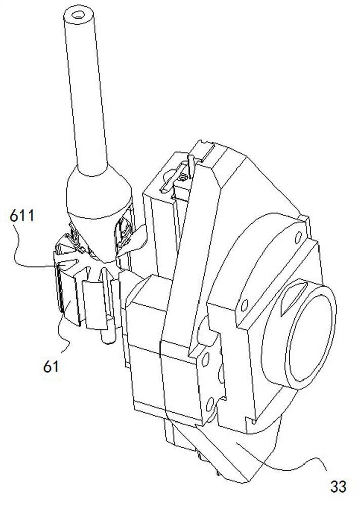
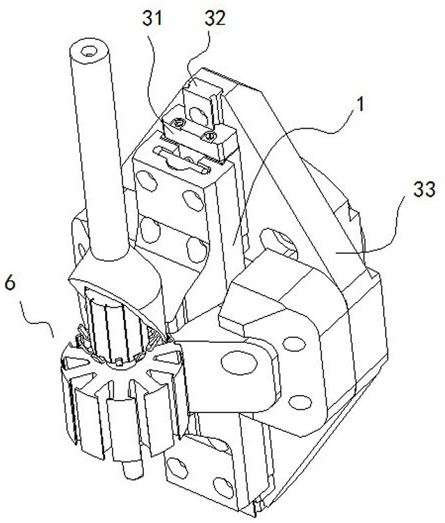
[0031] Please refer to Figure 1 to Figure 15 , the telescopic motor rotor winding device in the figure includes a first winding guide 1, a second winding guide 2, a guide sliding mechanism 3, a guide reset mechanism 4, and a guide telescopic Drive mechanism 5. The function of the first winding guide 1 and the second winding guide 2 is to lead the copper wire out from the fly fork 10 and wind it on the iron core 61 in a superimposed state, even if the copper wire has a height difference and is wound on the iron core of the rotor 6. On the core 61, the copper wire can be prevented from detaching from the hanging groove 611 due to the increased winding space through such a winding method. The function of the guide sliding mechanism 3 is to make the above-mentioned two guides slide up and down to realize telescopic action; the function of the guide reset mechanism 4 is to reset the above-mentioned two guides; The motion is converted into an up and down motion of the two guides ...


PUM


Abstract

The invention discloses a telescopic motor rotor winding device, which comprises a first winding guide, a second winding guide, a guide sliding mechanism, a guide reset mechanism, and a guide telescopic drive mechanism; the first winding guide The member and the second winding guide are spaced apart from each other and arranged symmetrically; the sliding mechanism of the guide includes a slide seat, a slide rail and a bracket. The invention can solve the technical problem of how to increase the winding space of the motor to prevent the winding from detaching from the hanging slot.

Description

technical field [0001] The invention provides a telescopic motor rotor winding device, specifically a telescopic motor rotor winding device in which high and low areas are formed on the micro motor rotor during the winding process to prevent the winding from falling out of the groove. Background technique [0002] The rotor of a DC motor is composed of an iron core, a winding, a commutator, and a rotating shaft; the iron core is composed of multiple punches, and each punch has multiple hanging slots for winding copper wires; the winding is copper wire winding forming. At present, such DC micro motors are mainly used in home appliances. At present, there is a special device for winding copper wires on the iron core. It uses a fly fork to wind the copper wires on the hanging groove of the iron core. The current device is generally Use a winding seat to fix the position of the copper wire on the iron core. The winding seat generally includes a horizontal positioning block and ...

Claims


Application Information

Patent Timeline
Patent Type & Authority Patents(China)
IPC IPC(8): H02K15/09
Inventor 李水军顾利威赵利灿赵博灵陈闰丰
Owner 绍兴智立机电科技有限公司
Learn More